
Fred

Made by remi-mazhar
About the project
A robotic hand, inspired by the biomechanics of a human hand.
Project info
Items used in this project
Hardware components

Story
Introduction
The aim of this project is to create a robotic hand, inspired by the biomechanics of a human hand.
Context
We are a small IT club in a high school with about 8 active members. As a very young club managed entirely by students, we are very proud to showcase this project, made in a few weeks with only about 50 euros of budget in total. Hope you will enjoy reading about this project as much as we enjoyed making it!
Goals
Our main goal is to be able to completely bend and unbend each finger independently. It is then possible to implement different hand gestures, such as a game of rock-paper-scissors. Secondary goals include grabbing objects, intermediate finger positions, and controlling bending/unbending speed. Eventually, the project could evolve to allow for more complex gestures, like lateral movements or controlling each phalanx independently.
Basic principle
In humans, muscles responsible for finger bending are not located inside one’s fingers : flexion is controlled by tendons, pulled by muscles in the forearm.
For each phalanx, there is one tendon on the inner side and on the outer side of the finger. Pulling on the extensor (outer) tendon causes the finger to unbend, and pulling on the flexor (inner) tendon causes it to bend.

There are numerous other tendons in hands, but these two are the most important for our project. In order to accurately replicate a human hand, we would need two flexor tendons (and two motor-muscles) for each finger. Instead, it is easier to have only one motor-muscle and one pair of tendons per finger for now. To bend the finger, the motor rotates so that it pulls on the extensor tendon and relaxes the flexor tendon. If the motor rotates in the opposite direction, the finger unbends.

Difficulties encountered and solutions
Architecture choice
Each finger is composed of 3 identical phalanxes (except for their size), except for the thumb, which only has 2. They are connected by joints capable of a 60° bend. Tendons go through each phalanx in tubes. The fingers are connected to a palm with no mechanical function, and the thumb is tilted compared to the other fingers. Tendons are extended though the palm and the wrist, and attached to motors in the forearm. These motors are servo motors (capable of orienting themselves in a precise given position, between 0 and 180°), and controlled by an arduino microcontroller board.

Manufacturing methods
The joints are made out of tubes rotating around a toothpick, like a hinge.
The tendons are fishing wires, thin and strong.
The phalanxes and the “forearm” are 3d-printed with resin, which allows for very complex and very precise geometry.
The palm is 3D-printed in PLA, less precise than resin, but allows for bigger parts.
Friction
With our first prototype, the force required to bend and unbend the finger was far too large. In order to fix this, we shifted the tendons away from the center of the finger, thereby providing more torque and decreasing the force needed to bend/unbend the finger.
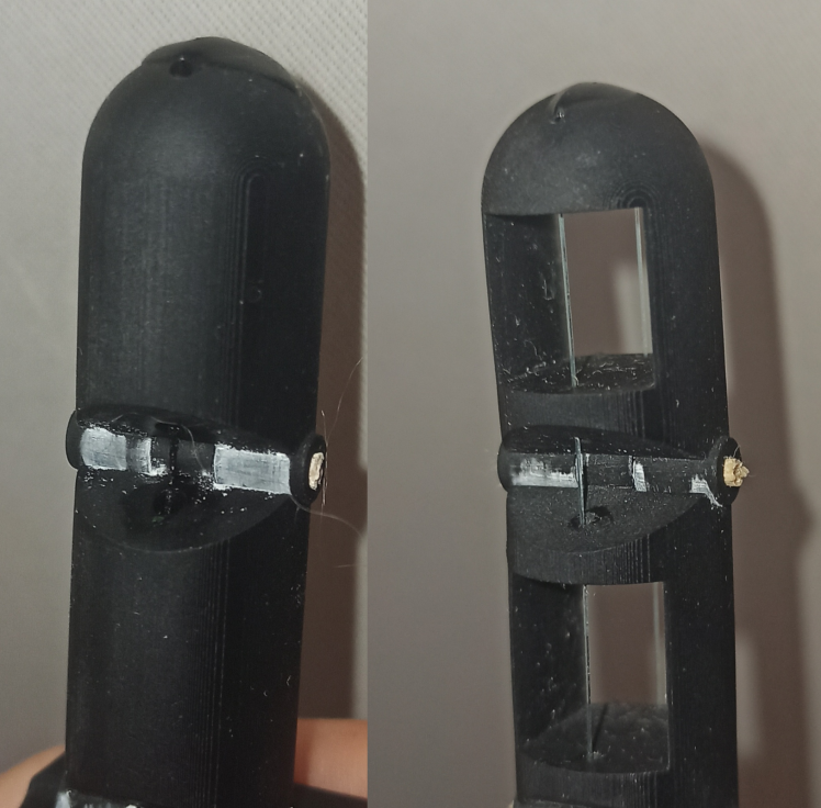
Moreover, we hollowed the phalanxes, to reduce the length of the tubes that the tendons have to slide through. This caused the flexion and extension of the finger to be far easier. We think friction was too high inside tubes, so hollowing the phalanxes reduced this friction.
An early prototype, non hollowed (left) VS hollowed version (right):
Asymmetry
We noticed that on our prototype, it was impossible to properly tighten the tendons: if they were tight when the finger was extended, the extensor tendon was loose when the finger was bent. We realised this was because of the distance between the tendons and the central axis : both of them were at the same distance until then, but the flexor tendons should have been closer by a factor of cos(30°) in order for the retracted length of wire (ΔL on this diagram) to be the same on both sides.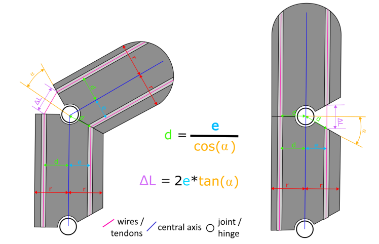
Tension
Tightening the tendons ended up being more difficult than anticipated. It is very difficult to glue the wire to the motor while maintaining it tightened. We decided to set up a system to adjust the position of the motor after the wires are glued. That way, if the wires are not properly tightened, we can slide the motors back a bit, which tightens the wires. To adjust the position of the motor, we attached it to a slider mounted on screws. We can then slide the motor back by tightening the screws.

Rigidity
The forearm was not sturdy enough because resin is slightly flexible, which made it hard to tighten the wires. In order to fix this, we adapted the geometry of the parts, to be able to insert two aluminum rods, insurring better parallelism between the left and right parts of the forearm, and better overall rigidity.

Circuit complexity
Even though servo motor connections are relatively simple in principle, the circuit contains more than 20 wires, which makes the circuit incomprehensible especially since the breadboard we used was too small. This made it difficult to find errors.

In order to reduce the number of wires needed, we made a printed circuit board. We used a plastic plate covered by a copper layer on which we 3d-print (with resin) the desired circuit. The pattern thus formed will serve as a mask. Then, we dissolve non-masked copper with a solution of acetic acid (vinegar), hydrogen peroxide, and sodium chloride (salt). The result is a circuit board on which we solder connectors. We can then directly connect the servo motors to these connectors, without the need for extra wires.


Final result
Here are videos of Fred's birth, on March 19th, around 10am.
Schematics, diagrams and documents
CAD, enclosures and custom parts
Code
Credits
Related products


Leave your feedback...