
Build A Tracker Using Gps, Cellular And A Flutter Mobile App

Made by kangmin-xu
About the project
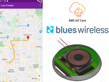
Learn how to build a person or asset tracking system using a Cellular- and GPS-enabled Notecard and a Flutter-based mobile app.
Project info
Difficulty: Moderate
Platforms: Amazon Web Services, Autodesk, Microsoft, Nordic Semiconductor, Blues Wireless
Estimated time: 2 days
License: GNU General Public License, version 3 or later (GPL3+)
Items used in this project
Hardware components

Software apps and online services
Story
Location tracking of people and/or assets is constantly in high demand. The challenge though is to achieve minimum power consumption and low cost. In this article, I'm trying to tackle both with the Notecard by Blues Wireless to explore the possibility of creating a low cost and low power tracking device.
Notecard is a prepaid System-on-Module that uses the NB-IoT or LTE-M cellular networks. It provides 500MB of cellular data for 10 years. There is no SIM or carrier subscription required compared to other traditional cellular tracking implementations.
When designing the tracker, users’ needs are also taken into consideration such as “continuous” GPS mode, which is essential for urgent tracking. Tracking fast movement during transportation is also critical. Sometimes the urgency requirements are contrary to low energy/cost. Most of the time, efforts will be made to minimize the power consumption by analyzing user’s behavior using motion sensors and geofencing safe zones. But in some extreme cases, tracking needs to be live all the time, and users have to understand the high power consumption and maybe high costs come with it.
Workflow of the system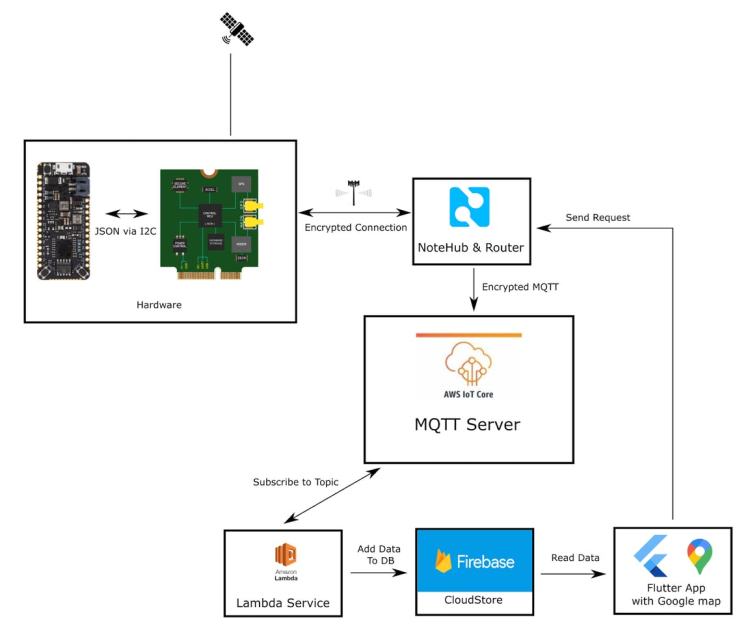
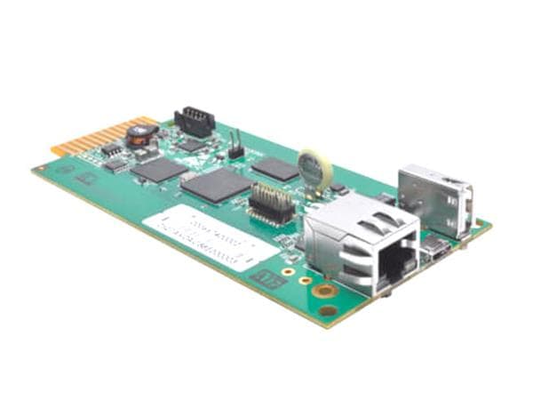
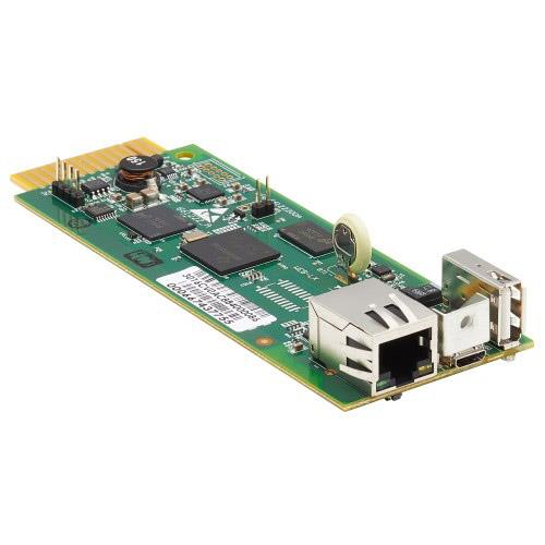
This is a general flowchart of the system. Hardware-wise, I use a Swan board, Notecard and Notecarrier-AF for the hardware prototypes. A more compact design can be accomplished by using a custom PCB and a MCU. Notecard is able to talk to the Blues Wireless cloud service Notehub directly and send encrypted events data through the cellular network.
Then all of the data is routed to AWS IoT Core, which is set up as a center distribution hub to connect different microservices, so that the system can be widely expanded later on.
Currently, I only use an AWS lambda service to subscribe to certain topics from MQTT Server and then push the JSON event data to Firebase’s cloud store since it’s relatively simple and friendly to mobile applications. You can certainly use any self hosted database such as MongoDB, SQL Server or MySQL.
The app subscribes to Firebase cloud store. Whenever there is an update, the code will refresh and the user interface will be updated accordingly, thus reducing the need for constant polling.
Here is the simplified data flow of the geolocation data: Notecard -> AWS IoT Core -> AWS Lambda -> Firebase -> User phone.
I will expand more on different components in the following sections.
Notecard Hands-onFirst, I tried to use a standalone Notecard for asset tracking. Here is my setup commands for the Notecard, using only JSON requests:
{"req":"card.restore","delete":true}
{"req":"hub.set","product":"COM.xx.xx","mode":"periodic","outbound":10,"inbound":20} {"req":"card.location.mode","seconds":600,"mode":"periodic"}
{"req":"card.location.track","start":true,"heartbeat":true,"hours":1}
This setup asks the Notecard to get GPS location data every 10 minutes if there are any motions detected. If no movement, data will still be synced every 1 hour. I can then get the data in Notehub.
There are a couple types of common data. You can also define your own custom data.
The most common one is session data called “_session.qo”. It looks something like this:
{
   "event":"bafbd3c1-xx-fd8636ae30b7",
   "session":"6d4b4648-xx-447fe95f7827",
   "best_id":"dev:xx",
   "device":"dev:xx",
   "product":"product:xx",
   "received":1649031204.68326,
   "routed":1649031207,
   "req":"session.begin",
   "when":1649031204,
   "file":"_session.qo",
   "body":{
      "why":"periodic inbound sync due"
   },
   "best_location_type":"tower",
   "best_lat":42.xx,
   "best_lon":-87.xx,
   "best_location":"xx IL",
   "best_country":"US",
   "best_timezone":"America/xx",
   "tower_when":1649031204,
   "tower_lat":42.x,
   "tower_lon":-87.xx,
   "tower_country":"US",
   "tower_location":"xx IL",
   "tower_timezone":"America/xx",
   "tower_id":"310,410,16665,53907217",
   "moved":1649030373,
   "orientation":"face-up",
   "rssi":-125,
   "sinr":8,
   "rat":"emtc",
   "bars":1,
   "voltage":4.545,
   "temp":23.562,
   "log":{
      "app:8075c5b1-1967-46de-adab-aec85cb35f6b/route:f958d63190a43459bc7544962a3383f1":{

      }
   }
}
It contains device information, cell tower information, last known location information and voltage, temp of the Notecard which covers almost everything for asset tracking. It’s pretty useful in building informative applications later on.
When GPS is running, it will get tracking data with the default name “_track.qo”.
Here is the “_track.qo” data.
{
"event":"4732158e-f6f4-473d-a1e0-9b1728041afe",
"session":"9edaa70e-e49b-4408-a31b-020444f3bf9a",
"best_id":"dev:xx",
"device":"dev:xx",
"product":"product:xx",
"received":1649628765.402938,
"routed":1649628768,
"req":"note.add",
"when":1649628739,
"file":"_track.qo",
"updates":1,
"body":{
"hdop":2,
"seconds":58,
"temperature":26.4375,
"time":1649628739,
"usb":true,
"voltage":4.546875
},
"best_location_type":"gps",
"best_lat":42.xx,
"best_lon":-87.xx,
"best_location":"xx, IL",
"best_country":"US",
"best_timezone":"America/xx",
"where_olc":"xx",
"where_when":1649628739,
"where_lat":42.xx,
"where_lon":-87.x,
"where_location":"xx, IL",
"where_country":"US",
"where_timezone":"America/xx",
"tower_when":1649628764,
"tower_lat":42.x,
"tower_lon":-87.x,
"tower_country":"US",
"tower_location":"xx IL",
"tower_timezone":"America/xx",
"tower_id":"310,410,16665,54106385",
"log":{
"app:8075c5b1-1967-46de-adab-aec85cb35f6b/route:f958d63190a43459bc7544962a3383f1":{
}
}
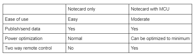
}However, I have an issue with the Notecard-only approach, it doesn’t allow changing configurations through an external HTTP post request. For example, you cannot change the interval value through an external network command.
Therefore a MCU connected approach is the only option, with the MCU connecting to a Notecard. It unlocks the full potential of a Notecard, since you can communicate with the Notecard whenever it needs without worrying about cell connection. Also, configurations of the Notecard can be changed over the air. There are so many things you can achieve.
Here I only use the Remote command function. Notecard will toggle its ATTN pin to HIGH when there are interrupts. Interrupts can be remote HTTP request, motion, geofencing related. When the MCU wakes up, it will get the requested message and change the configuration of Notecard to the related mode, such as LIVE mode or NORMAL mode in asset tracking.
Comparison of Standalone-Notecard vs Notecard with MCU:
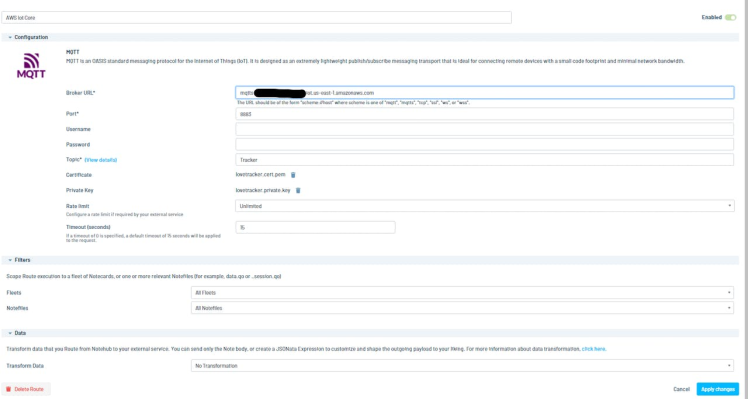
First, data is routed from NoteHub to AWS IoT Core.
Create an IoT device in AWS IoT Core and download the credentials including private key, certificate and root CA file.
Put the private key and certificate file in the MQTT settings in the router page below and enter the AWS IoT Endpoint.
From here all event data will be routed to AWS IoT core, it serves as your central MQTT hub, you can also use another MQTT server or host your own MQTT server using Mosquitto MQTT Broker.
In the AWS IoT Core Act → Rules, Setup lambda functions.

The AWS Lambda function is really simple. Here is the python code.
import json
import firebase_admin
from firebase_admin import credentials
from firebase_admin import firestore

# Use the application default credentials
cred = credentials.Certificate("./lovetracker-be488-xx.json")
firebase_admin.initialize_app(cred, {
'projectId': 'xx',
})
db = firestore.client()
local_col = db.collection(u'location_data')

def lambda_handler(event, context):
    id = event['event']
    local_col.document(id).set(event)
    return {
    'statusCode': 200,
    'body': json.dumps('Hello from Lambda!')
    }
I had an issue when deploying the Python code to AWS Lambda. The reason is that AWS lambda is using amazon linux, which does not work with Cloud Firestore Library that was installed in Windows. So I have to manually build python code inside a docker container using Amazon Linux docker image.
Here is the docker file I use to reinstall the firebase_admin module:
FROM amazonlinux:2.0.20210126.0
RUN yum -y groupinstall "Development Tools" &&
yum -y install openssl-devel bzip2-devel libffi-devel &&
yum -y install wget &&
wget https://www.python.org/ftp/python/3.8.7/Python-3.8.7.tgz &&
yum install -y tar &&
yum install -y gzip &&
tar xvf Python-3.8.7.tgz &&
cd Python-3.8*/ &&
./configure --enable-optimizations &&
make altinstall &&
yum install -y zip &&
yum clean all
RUN python3.8 -m pip install --upgrade pip &&
python3.8 -m pip install virtualenv
RUN python3.8 -m venv myvenv
RUN source myvenv/bin/activate
RUN pip install firebase-admin -t ./python
RUN deactivate
RUN zip -r python.zip ./python/
Of course, you can use your own server to serve as the bridge between MQTT hub and a database.
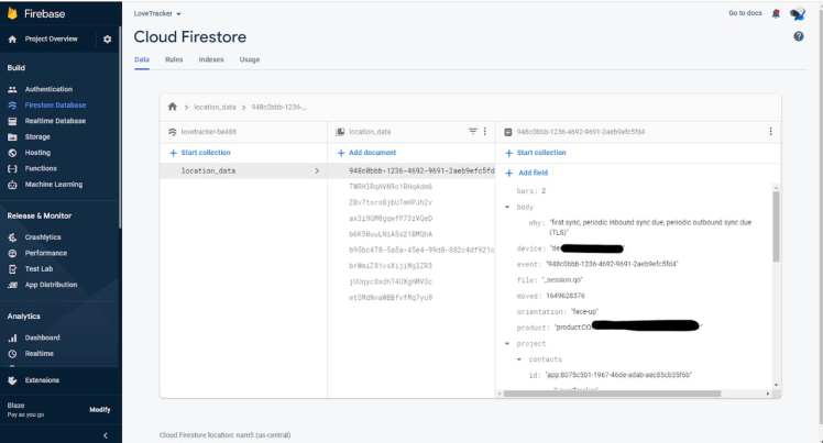
Finally, data is routed to the Firebase cloud store.
I used an official Arduino example external interrupt as a template. The Swan communicates with the Notecard through I2C and setup as normal mode.
When the device is initialized, it is set up as Normal mode to conserve battery. GPS data is acquired every 10 minutes, and syncs with Notehub.
Upon user request, Live mode can be activated when a remote client sends a HTTP Post request with the request content LIVE.
The address of the request is https://api.notefile.net/req?product=[ProductID]&device=[DeviceID]
You may need to get a Session token in the header for authentication purposes, see here for details.
Here is the body of the post request:
{
   "req":"note.add",
   "file":"remote-command.qi",
   "body":{
      "set-mode":"NORMAL"
   }
}
Here is the Arduino Source Code:
#define serialDebugOut Serial

#include <Notecard.h>
#include <Wire.h>


#define ATTN_INPUT_PIN  5     // Any digital GPIO pin on your board

// #define serialNotecard Serial1

#define PRODUCT_ID "xx.xx.xx"
Notecard notecard;


int liveUpdateInterval = 30;  // every 30 seconds update live position
int normalUpdateInterval = 30; //every 30 mintues update current position
int liveMode = false;

#define INBOUND_QUEUE_NOTEFILE    "remote-command.qi"
#define INBOUND_QUEUE_COMMAND_FIELD "set-mode"

// Set to true whenever ATTN interrupt occurs
static bool attnInterruptOccurred;

// Forwards
void attnISR(void);
void attnArm();

void changeToLiveMode()
{
    J *req = notecard.newRequest("hub.set");
    JAddStringToObject(req, "product", PRODUCT_ID);
    JAddStringToObject(req, "mode", "periodic");
    JAddNumberToObject(req, "outbound", 10);
    JAddNumberToObject(req, "inbound", 1);
    notecard.sendRequest(req);


    req = notecard.newRequest("card.location.mode");
    JAddStringToObject(req, "mode", "periodic");
    JAddNumberToObject(req, "seconds", 60);
    notecard.sendRequest(req);
}

void changeToNormalMode()
{
    J *req = notecard.newRequest("hub.set");
    JAddStringToObject(req, "product", PRODUCT_ID);
    JAddStringToObject(req, "mode", "periodic");
    JAddNumberToObject(req, "outbound", 10);
    JAddNumberToObject(req, "inbound", 20);
    notecard.sendRequest(req);

    req = notecard.newRequest("card.location.mode");
    JAddStringToObject(req, "mode", "periodic");
    JAddNumberToObject(req, "seconds", 600);
    notecard.sendRequest(req);
}

void setup() {
  // put your setup code here, to run once:
#ifdef serialDebugOut
    delay(2500);
    serialDebugOut.begin(115200);
    notecard.setDebugOutputStream(serialDebugOut);
#endif

#ifdef serialNotecard
    notecard.begin(serialNotecard, 9600);
#else
    Wire.begin();
    notecard.begin();
#endif

    delay(10000);


    J *req = notecard.newRequest("hub.set");
    JAddStringToObject(req, "product", PRODUCT_ID);
    JAddStringToObject(req, "mode", "periodic");
    JAddNumberToObject(req, "outbound", 10);
    JAddNumberToObject(req, "inbound", 30);
    notecard.sendRequest(req);


    req = notecard.newRequest("card.attn");
    JAddStringToObject(req, "mode", "disarm,-files");
    notecard.sendRequest(req);

    req = notecard.newRequest("card.attn");
    const char *filesToWatch[] = {INBOUND_QUEUE_NOTEFILE};
    int numFilesToWatch = sizeof(filesToWatch) / sizeof(const char *);
    J *filesArray = JCreateStringArray(filesToWatch, numFilesToWatch);
    JAddItemToObject(req, "files", filesArray);
    JAddStringToObject(req, "mode", "files");
    notecard.sendRequest(req);

    pinMode(ATTN_INPUT_PIN, INPUT);
    attachInterrupt(digitalPinToInterrupt(ATTN_INPUT_PIN), attnISR, RISING);

    attnArm();

    changeToNormalMode();
}


void attnArm()
{

    // Make sure that we pick up the next RISING edge of the interrupt
    attnInterruptOccurred = false;

    // Set the ATTN pin low, and wait for the earlier of file modification or a timeout
    J *req = notecard.newRequest("card.attn");
    JAddStringToObject(req, "mode", "reset");
    JAddNumberToObject(req, "seconds", 120);
    notecard.sendRequest(req);

}

// Interrupt Service Routine for ATTN_INPUT_PIN transitions rising from LOW to HIGH
void attnISR()
{
    attnInterruptOccurred = true;
}

void loop() {
  // put your main code here, to run repeatedly:

      if (!attnInterruptOccurred) {
        return;
    }

    attnArm();
        // Process all pending inbound requests
    while (true) {

        // Get the next available note from our inbound queue notefile, deleting it
        J *req = notecard.newRequest("note.get");
        JAddStringToObject(req, "file", INBOUND_QUEUE_NOTEFILE);
        JAddBoolToObject(req, "delete", true);
        J *rsp = notecard.requestAndResponse(req);
        if (rsp != NULL) {

            // If an error is returned, this means that no response is pending.  Note
            // that it's expected that this might return either a "note does not exist"
            // error if there are no pending inbound notes, or a "file does not exist" error
            // if the inbound queue hasn't yet been created on the service.
            if (notecard.responseError(rsp)) {
                notecard.deleteResponse(rsp);
                break;
            }

            // Get the note's body
            J *body = JGetObject(rsp, "body");
            if (body != NULL) {

                // Simulate Processing the response here
                char *myCommandType = JGetString(body, INBOUND_QUEUE_COMMAND_FIELD);
                notecard.logDebugf("INBOUND REQUEST: %snn", myCommandType);

                char cmp_val[] = "LIVE";

                if (strcmp(myCommandType,cmp_val) == 0)
                {
                    notecard.logDebugf("Change to LIVE MODE");
                    if (liveMode == false)
                    {
                      liveMode = true;
                      changeToLiveMode();
                    }
                }
                else
                {
                    notecard.logDebugf("Change to Normal MODE");
                    if (liveMode == true)
                    {
                      liveMode = false;
                      changeToNormalMode();
                    }

                }
            }

        }
        notecard.deleteResponse(rsp);
    }

}For the Flutter mobile app, we need to connect to the firestore to get location data. Location data storage is a document-based storage where each event is a JSON string. Event ID is used as the key of the JSON document.
I use the Firebase Flutter library to listen to firestore changes. Whenever there is new data added, the StreamBuilder will be called to rebuild the whole GoogleMap structure with the latest location data.
Listen to Firestore changes:
  final Stream<QuerySnapshot> _locStream =
  FirebaseFirestore.instance.collection('location_data').snapshots();

  @override
  Widget build(BuildContext context) {
    return StreamBuilder<QuerySnapshot>(
      stream: _locStream,
      builder: (BuildContext context, AsyncSnapshot<QuerySnapshot> snapshot) {
        if (snapshot.hasError) {
          return const Text("Something went wrong");
        }

        if (snapshot.connectionState == ConnectionState.waiting) {
          return const Text("Loading");
        }

        return GoogleMap(
            onMapCreated: _onMapCreated,
            initialCameraPosition: CameraPosition(
              target: LatLng(latestLat, latestLng),
              zoom: 11.0,
            ),
            markers: Set<Marker>.of(markers.values),
            polylines: Set<Polyline>.of(polylines.values));
      },
    );
  }
Below is the function to add a marker on a Google Map. The code will pick the most recent location and add the marker to the marker list.
void _add(lat, lng, markerNote) {
final String markerIdVal = 'marker_id_$_markerIdCounter';
_markerIdCounter++;
final MarkerId markerId = MarkerId(markerIdVal);
final Marker marker = Marker(
markerId: markerId,
position: LatLng(lat, lng),
infoWindow: InfoWindow(title: markerNote, snippet: '*'));
markers[markerId] = marker;
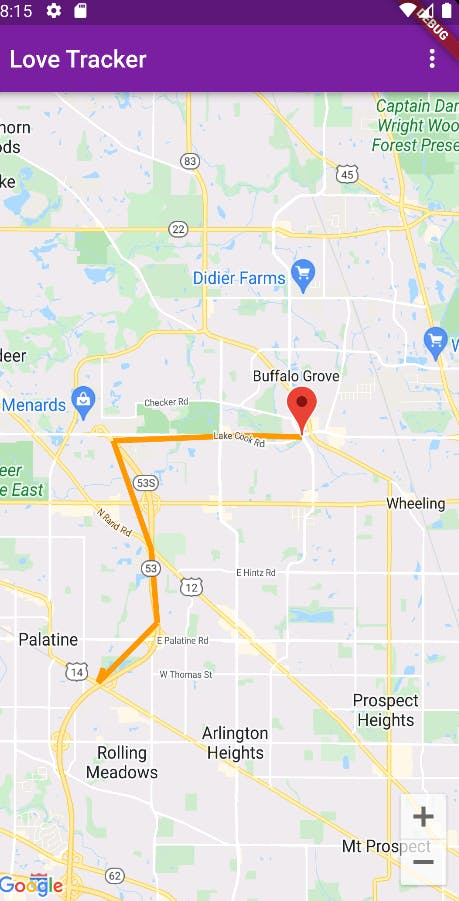
}Polylines represent the history of asset movements. The code will pick recent tracks and plot the movements. To further improve it. Tracker needs to be able to differentiate different types of movements such as in car, running, walking and even on boat. That will give users a better understanding of the movements.
void _add_poly_line(LatLng curPoint, LatLng prePoint) {
    final int polylineCount = polylines.length;

    final List<LatLng> points = <LatLng>[];

    points.add(prePoint);
    points.add(curPoint);

    // print('add poly_line');

    final String polylineIdVal = 'polyline_id_$_polylineIdCounter';
    _polylineIdCounter++;
    final PolylineId polylineId = PolylineId(polylineIdVal);

    final Polyline polyline = Polyline(
        polylineId: polylineId,
        consumeTapEvents: true,
        color: Colors.orange,
        width: 5,
        points: points);

    polylines[polylineId] = polyline;
  }
With markers and polylines, we can finally plot them on the google map. Below code plots everything on the Google map.
for (var element in snapshot.data!.docs) {
  var fileName = element['file'];

  print(fileName);
  if (fileName == '_track.qo') {
    var lat = element['where_lat'];
    var lng = element['where_lon'];
    var when = element['when'];
    var id = element['event'];

    var tempDict = {
      'id': element['event'],
      'lat': element['where_lat'],
      'lng': element['where_lon'],
      'timestamp': element['when']
    };

    latlngList.add(tempDict);

    if (when >= timestamp) {
      latestLat = lat;
      latestLng = lng;
      timestamp = when;
    }
  }
}

if (latlngList.isNotEmpty) {
  latlngList.sort((a, b) => a['timestamp'].compareTo(b['timestamp']));
}

// Add Polylines
for (var i = 0; i < latlngList.length - 1; i++) {
  var curPos = latlngList[i];
  var nextPos = latlngList[i + 1];

  var dis = distance(
      curPos['lat'], nextPos['lat'], curPos['lng'], nextPos['lng']);

  print('distance=' + dis.toString());

  if (dis > 100.0) {
    _add_poly_line(LatLng(curPos['lat'], curPos['lng']),
        LatLng(nextPos['lat'], nextPos['lng']));
  }
}

if (latestLat != 0.0 && latestLng != 0.0) {
  var date = DateTime.fromMillisecondsSinceEpoch(timestamp * 1000);

  _add(latestLat, latestLng, DateFormat().format(date));
  print('latest_lat=' + latestLat.toString());
  print('latest_Lng=' + latestLng.toString());
  print(timestamp);
}

return GoogleMap(
    onMapCreated: _onMapCreated,
    initialCameraPosition: CameraPosition(
      target: LatLng(latestLat, latestLng),
      zoom: 11.0,
    ),
    markers: Set<Marker>.of(markers.values),
    polylines: Set<Polyline>.of(polylines.values));
}
Users can select LIVE mode or NORMAL mode under the drop down menu. And the request will be directly sent to the Notecard and settings will be changed accordingly.
Power consumption is key to any low power application, as the end user definitely doesn’t want to charge every day. One week to one month per charge will be ideal. Users can also change intervals to increase power efficiency.
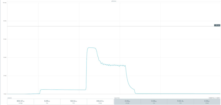
I recorded the current draw from the Notecard for one hour to study its current draw pattern.
Here is the general view.
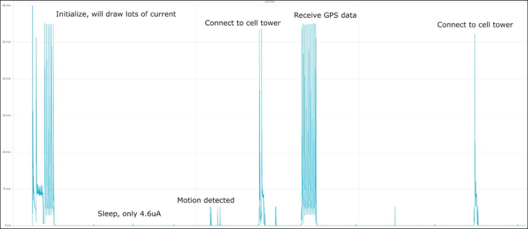
There are couples sections to discuss. First is the cellular connection and syncing phase, it usually takes 40 to 60 seconds. Notecard will search for nearby cell towers and sync events between itself and notehub. Highest current draw is around 50mA.
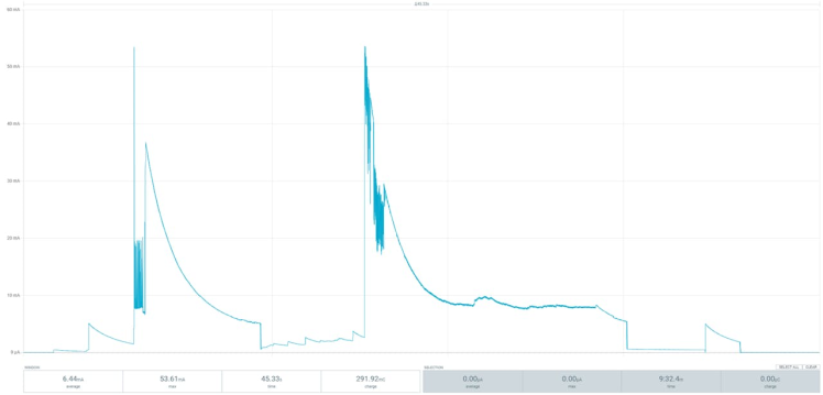
Second phase is the GPS data gathering phase. Accurate GPS is searched for about 1 minute. You can see the current cycling pattern. Highest current draw is around 50mA.

There is a little current pattern when I create a little motion during sleep. It seems the accelerometer gets triggered and ready to start a GPS session. It’s only 5mA at its peak and less than 500ms, almost neglectable.
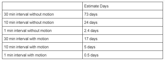
Here I assume using a 1000mAh battery to calculate the days it can last under different situations. Below is the result.
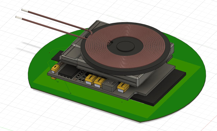
The initial circuit board design includes a wireless charging module for contactless charging, 8 x NeoPixel leds for status indicator, a MCU for controlling peripherals and communicating with Notecards. The empty space can be used to add PCB antennas for cellular and GPS. The 8 NeoPixels are distributed around the circuit board to provide an interactive way to work with kids.
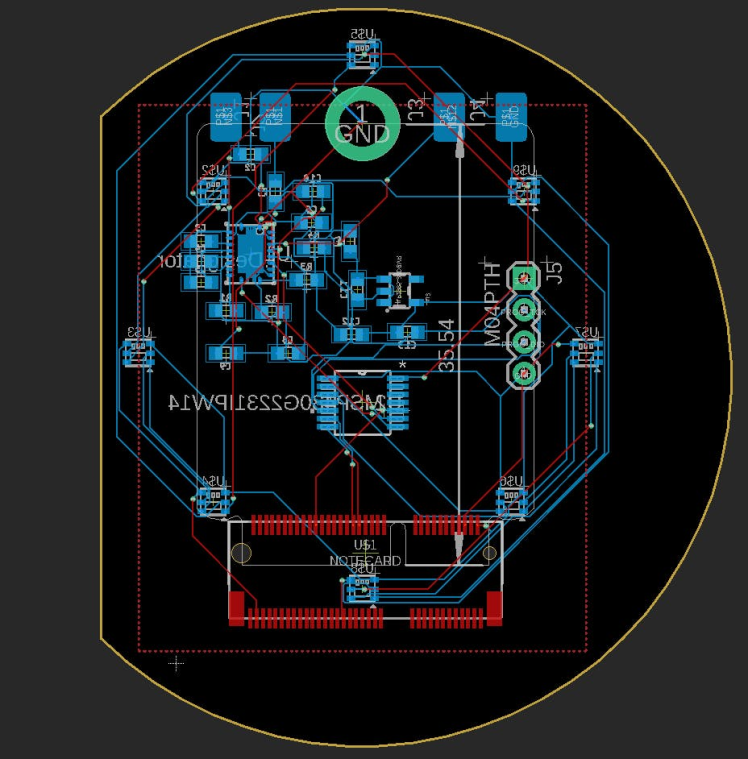
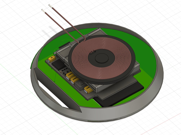
Battery and the wireless charging receiver are stacked on top of the PCB.
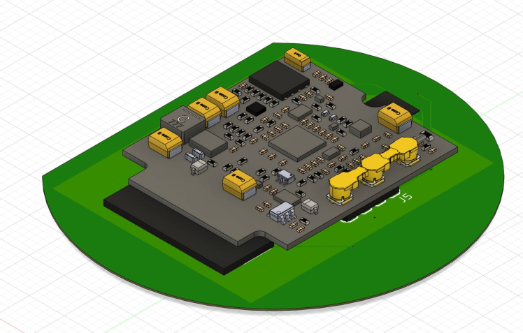
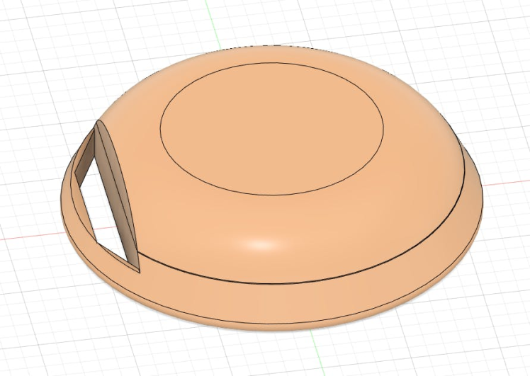
Case is designed with a hookable opening for any attachment need.
Final rendering of the tracker. Diameter is 2.3 inch / 58mm. A kid should be able to hold it comfortably. It can also be attached easily to a backpack, lunch bag, or car seats.
The purpose of this project is to explore the feasibility of using Notecard as a low-cost and low-power person/object tracking device. It’s more than capable of doing so. It has so many potentials as a tracking device yet it has a very easy interface to work with. It saves developers from tedious cellular modem communication and debugging processes and replaces them with high level APIs. Its router enables MQTT or HTTP redirects, allowing developers to integrate with any external web/app applications.
Overall, it’s a low-cost and easy-to-develop cellular IoT device with so many possibilities!
Schematics, diagrams and documents
CAD, enclosures and custom parts
Code
Credits
Related products


Leave your feedback...