

Build A Robot Buggy
Made by Raspberry Pi / Kids & Family / Robotics
About the project
In this project you will build a robot buggy that you can program to move around using simple Python commands.
Project info
Difficulty: Moderate
Platforms: Raspberry Pi
Estimated time: 1 day
License: Creative Commons Attribution CC BY version 4.0 or later (CC BY 4+)
Items used in this project
Hardware components


View all
Hand tools and fabrication machines
Story
What you will need
- Note that not all of the following hardware is required to create the buggy. However, if you are planning to add autonomous capability (self-driving) to your robot buggy, then you will need additional bits in the ‘optional’ list.
Hardware

Basic buggy
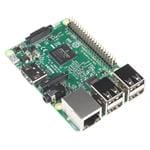
- Raspberry Pi 3
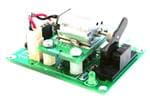
- Motor controller board
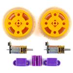
- 2 × 3V - 6V DC motors
- 2 × wheels
- 1 × AA battery holder (for 4 AA batteries)
- 4 × AA batteries
- Ball caster
- Wire or jumper leads
- A USB Battery pack
- Screw driver
- Soldering iron and solder
- Wire strippers
- Small cardboard or plastic box and glue/tape
Optional additional components
- Breadboard
- VL53L0X time-of-flight range finder or ultrasonic distance sensor
- 2 × line following sensors
- 18650 battery, battery clip, USB charge/discharge board (or USB power bank)You can view all the required components on this AliExpress Wish List, but they can be ordered/bought anywhere, and alternatives are available.
Software
- The latest version of the Raspbian operating system
Additional extras
- Small cardboard box
- Adhesives (duct tape/putty/glue)
Assembling the motors and board
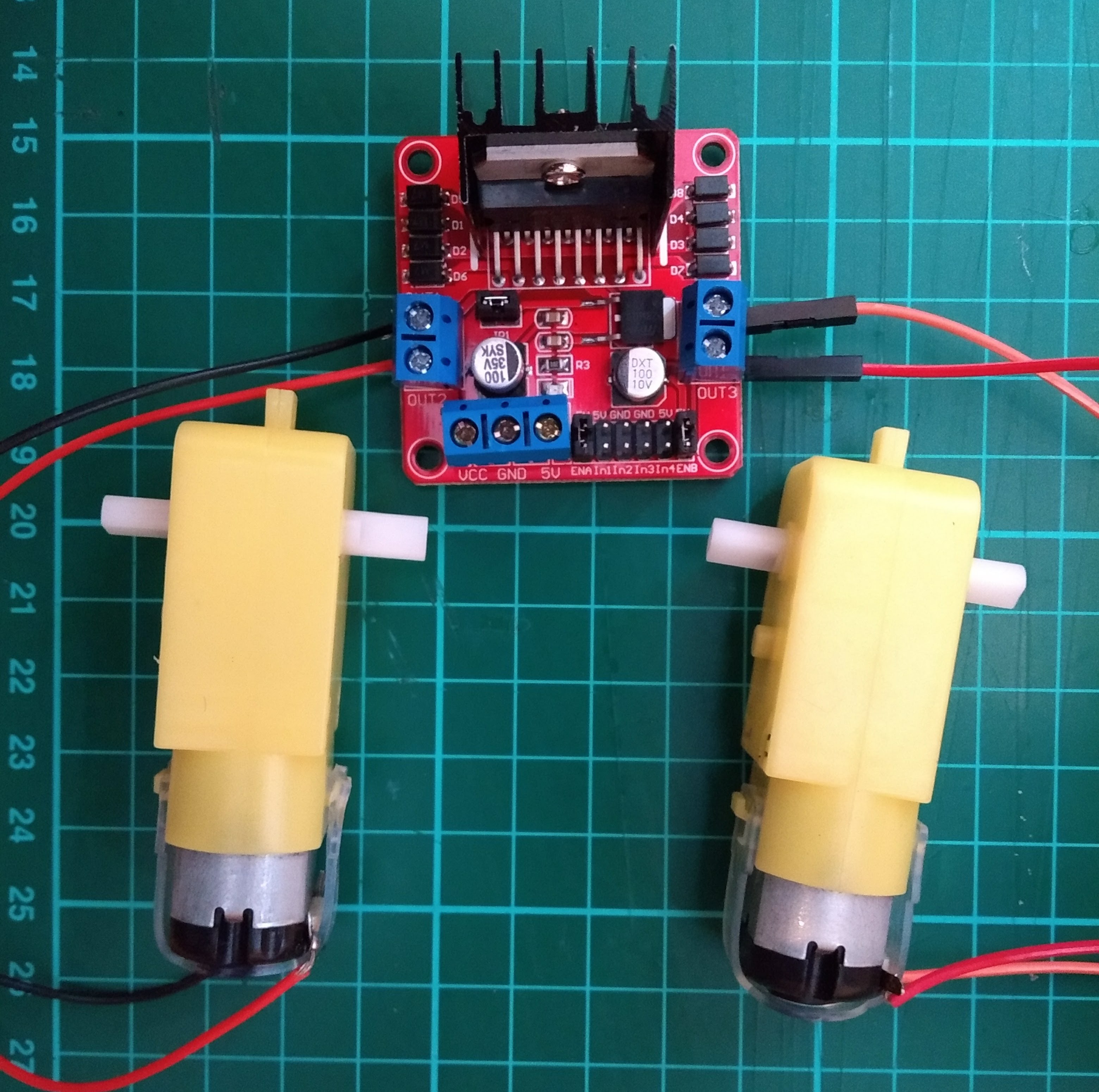
The first thing you will want to do is to connect your motor controller board to your Raspberry Pi, the battery pack, and your two motors, to test that they are all working.
The instructions here are for L298N Dual H Bridge DC Stepper Motor Driver Controller Board, and they will be pretty similar for most motor controller boards. Check the documentation for your board if you are using a different one.
Soldering wires to your motors
Most motors you can buy don’t have wires, so you will need to solder these on. If you have never soldered before, then have a look at our Getting started with soldering resource.
Strip the ends of the wires to reveal the metal core.
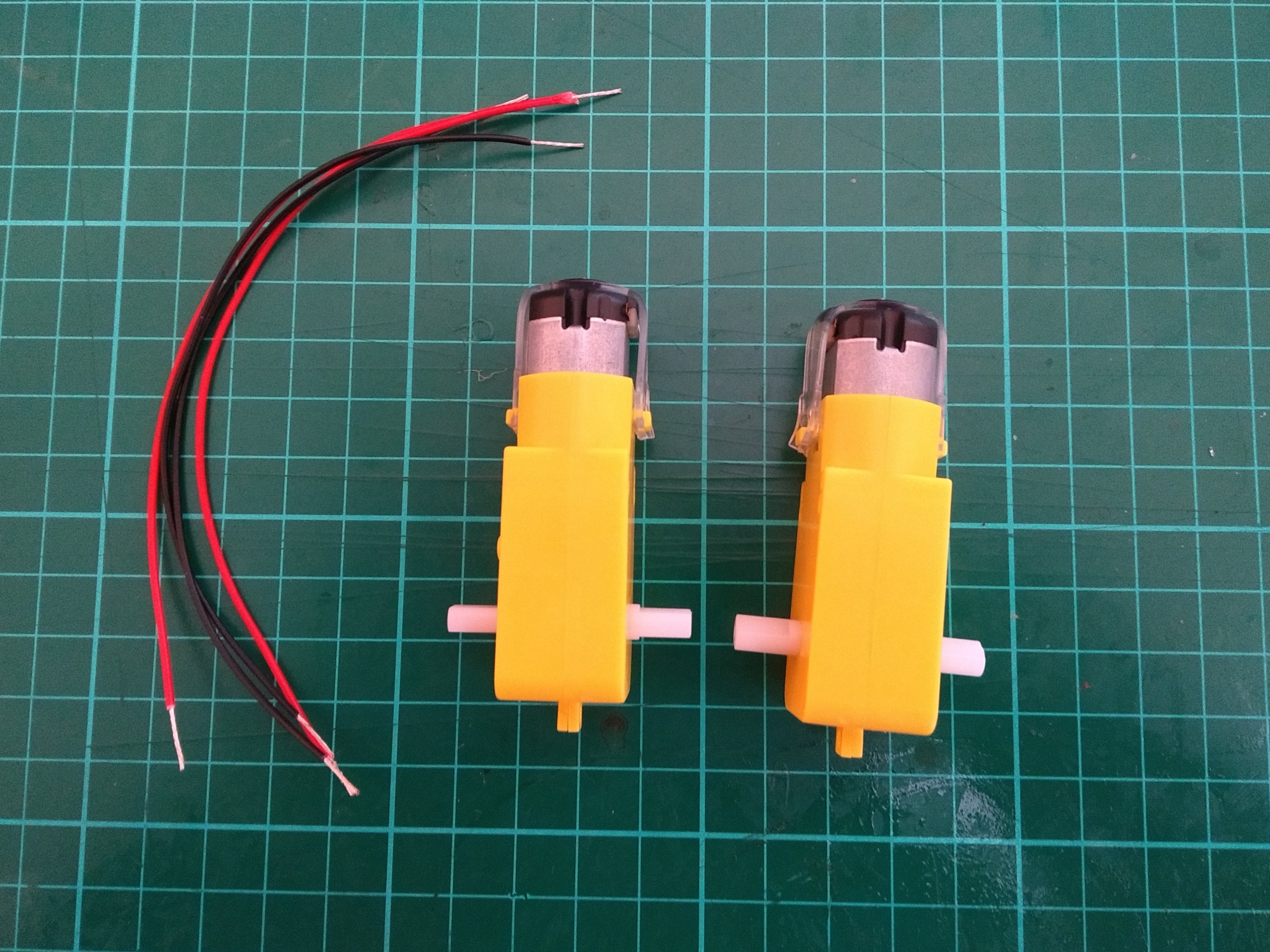
Remove the plastic clip from the motor to make soldering to the contacts easier. You can do this with a screwdriver.
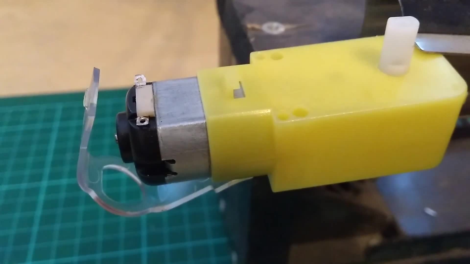
Solder the wires to each of the terminals on the motor. It doesn’t matter which wire goes to which terminal. The reattach the plastic clips.
Trim the tips of the wires to ensure they do not touch the metal casing of the motor. It’s also a good idea to wrap the ends of the motors in tape, to stop the soldered joints from breaking.
Connect the motors to the board
You will need to connect the motors to the board. For this you will require a small screwdriver.
Using a screwdriver, loosen the screws in the terminal blocks labeled UT1, OUT2, OUT3, and OUT4. Have a look at the documentation for your board if your labels are different. Strip the ends of the wires (you can snip off the male or female ends if you need to) and insert the stripped ends of wire into the terminal blocks.
Tighten the screws up so that the wires are held firmly in the terminal blocks.
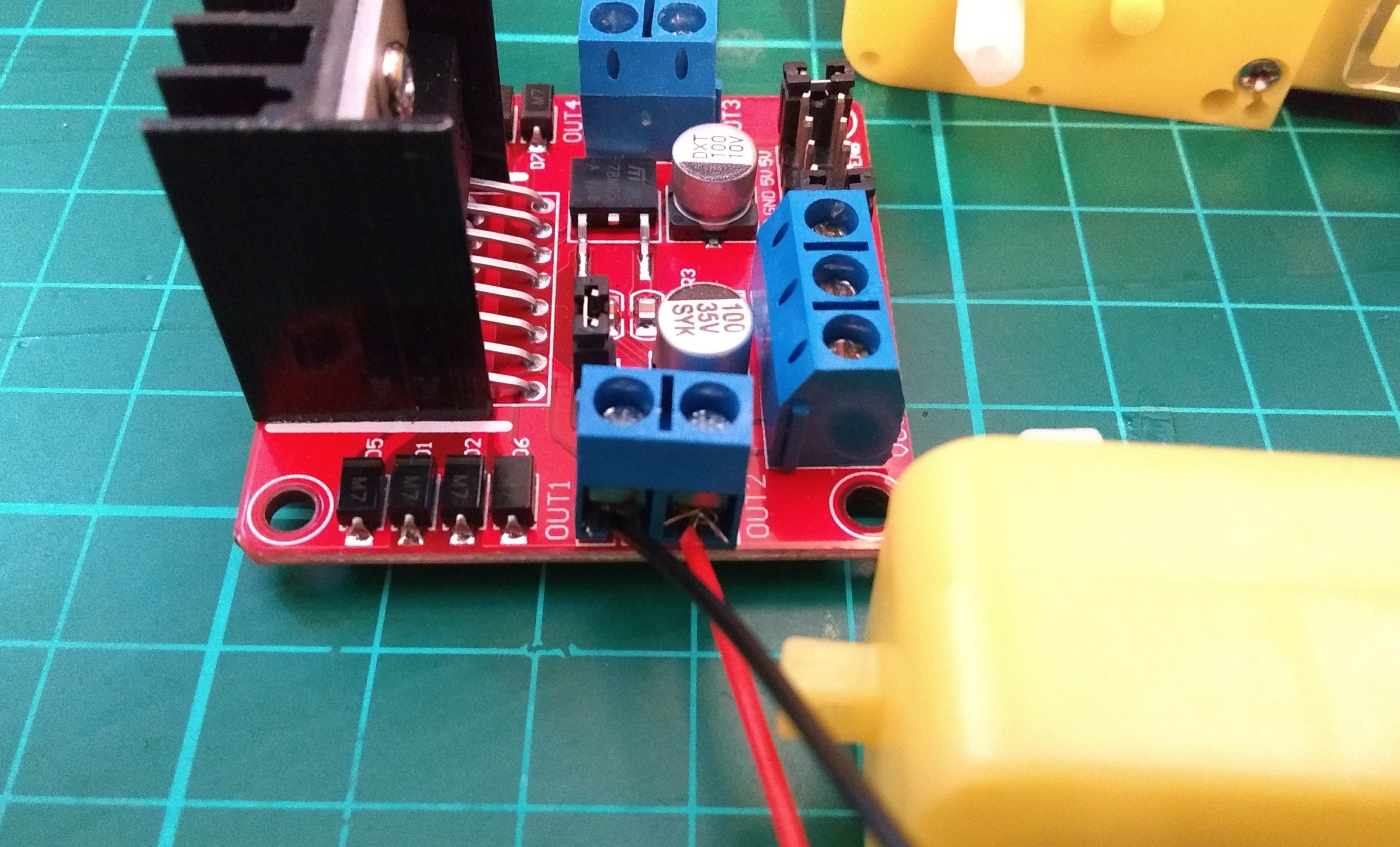
Powering the motors
The motors require more power than the Raspberry Pi can provide. Therefore, you will use four AA batteries to power them.
Loosen the screws in the terminal blocks labeled VCC, GND, and 5V. Take the AA battery holder and insert the red wire into the VCC terminal block. The black wire goes into the GND block. It is important that you get this the correct way around.
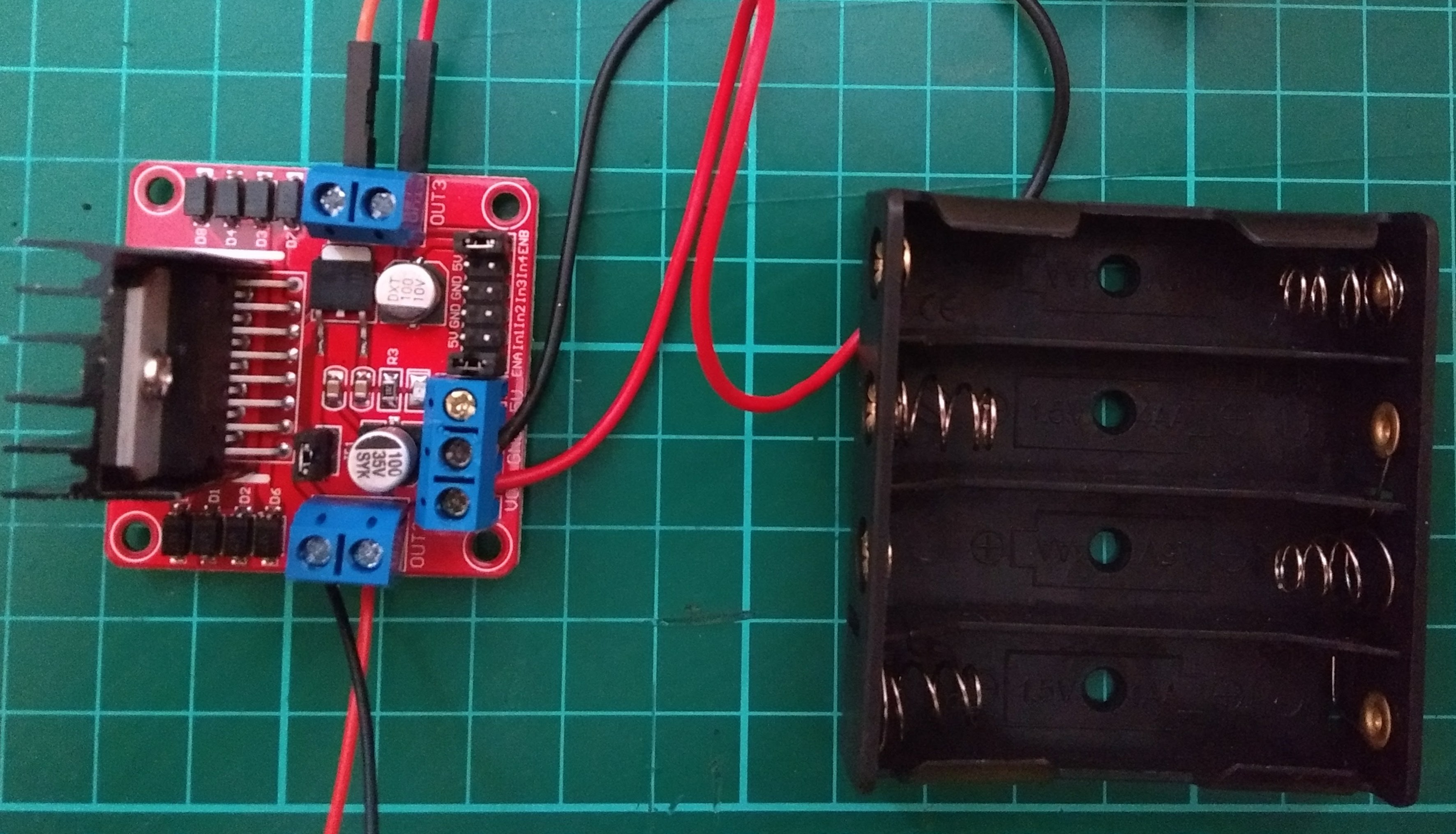
Tighten the screws so that the wires are held firmly in place.
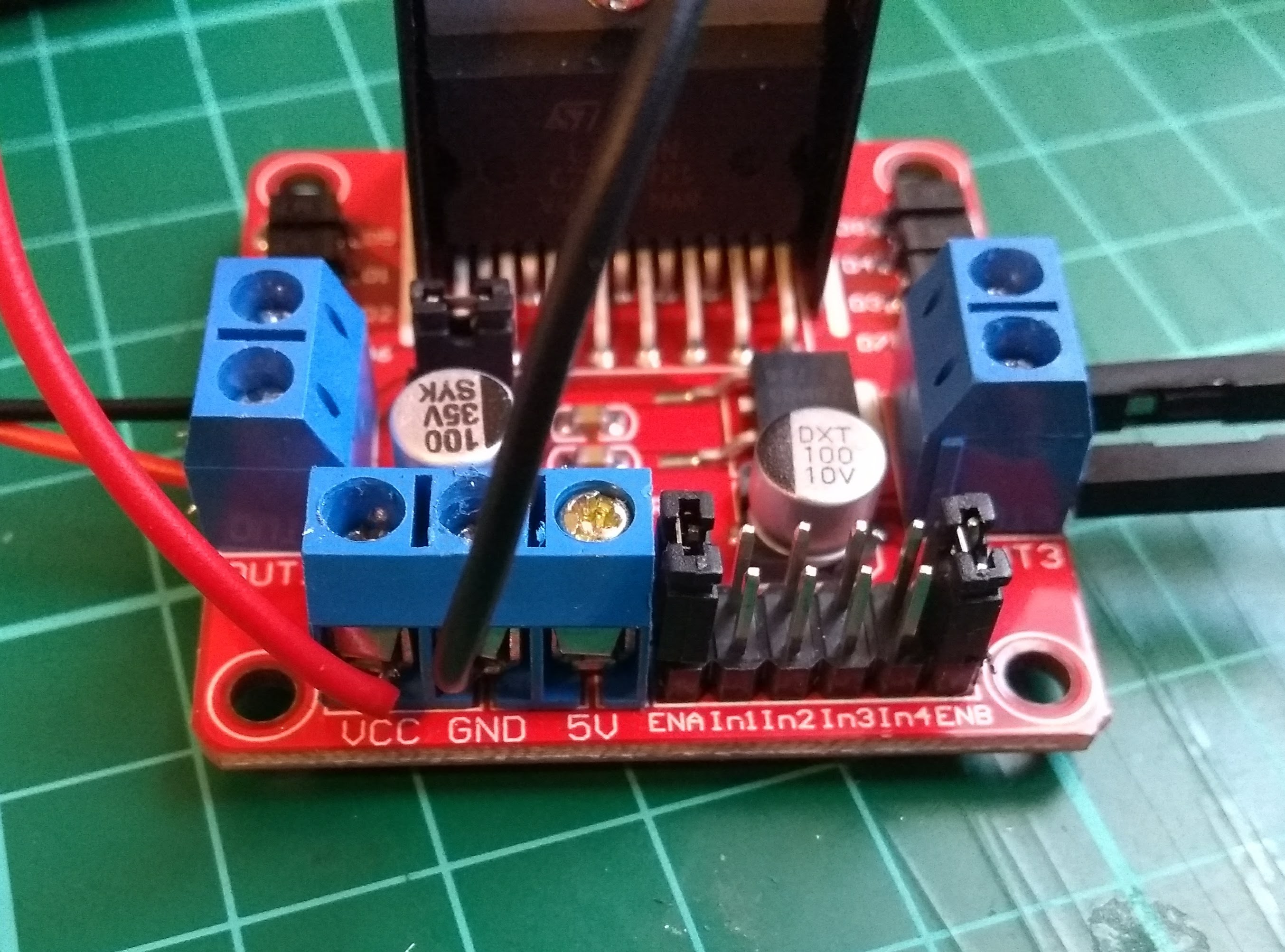
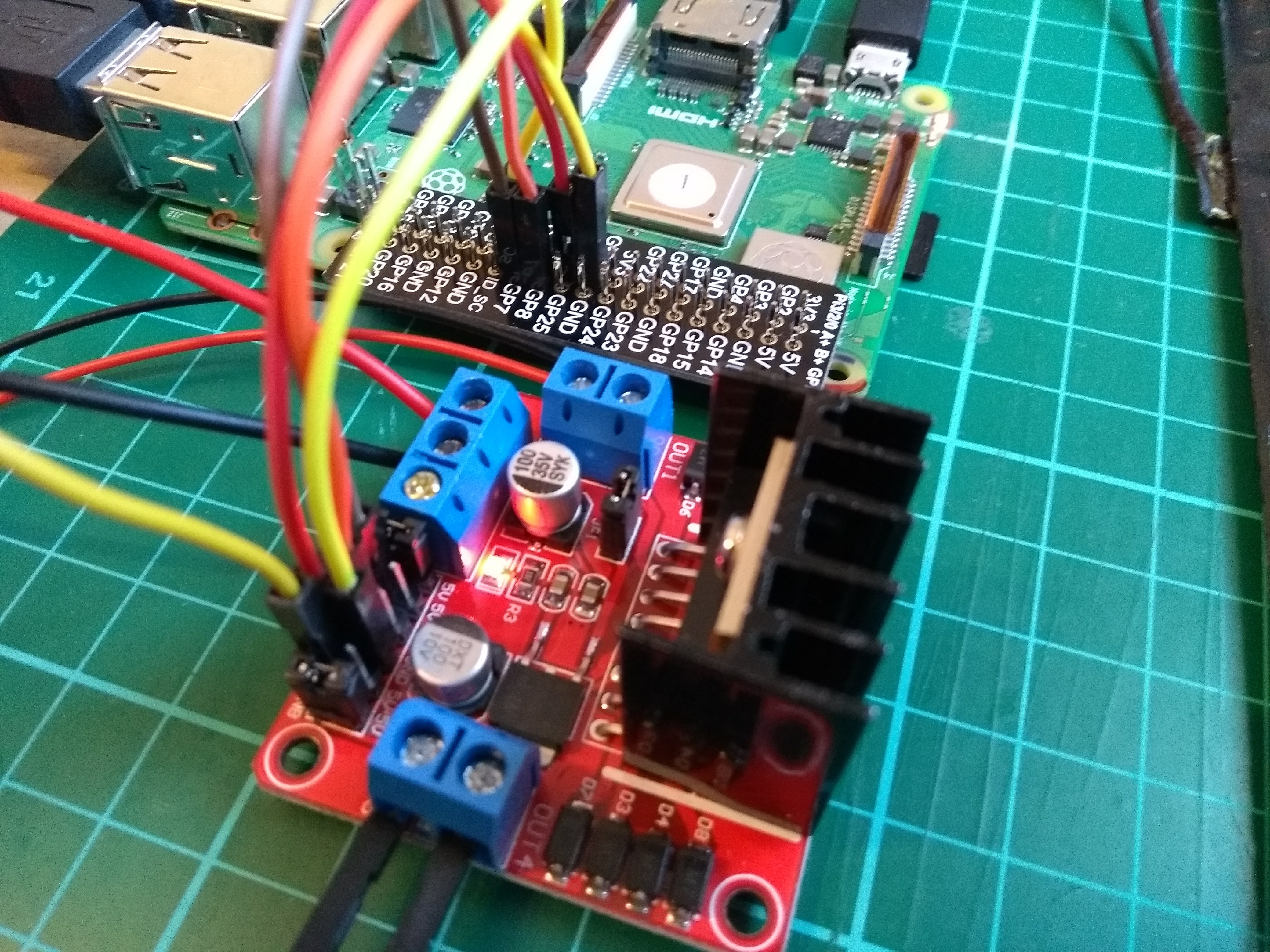
Connecting the board to your Raspberry Pi
The board used in this project needs to be wired to the Raspberry Pi. Other boards may connect differently, and some boards can simply be placed onto the Raspberry Pi GPIO pins as a HAT. Make sure you look at the documentation for your board to see whether this is the case.
On the board used here there are pins labeled In1, In2, In3, and In4, as well as two GND pins. Which GPIO pins on your Pi that you use is up to you; in this project, GPIO 7, 8, 9, and 10 have been used.
Use five female-to-female jumper leads to connect the Raspberry Pi GPIO pins to the pins on the motor controller board.
GPIO pin connects to board pin
7 <–> In1
8 <–> In2
9 <–> In3
10 <–> In4
GND <–> GND
If your board does not have a GND pin, then strip the end of the female to female wire and secure it into the GND terminal block that your battery pack feeds into.
Left, right, forward, backward
You need to figure out which is your left motor and which is your right motor. You also need to know which way they are driving to go forward, and which way they are driving to go backwards.
Choose one of the motors. Use a marker pen to label it ‘right’ and draw an arrow on it to indicate which way is forward. Label the other motor ‘left’ and draw an arrow on it pointing in the same direction as your first one.

Now open mu from the Raspberry Pi Programming menu.
Type the following to import the Robot class and create a Robot object. You can name it anything you like. In this resource, the robot is called robby.
- from gpiozero import Robot
- robby = Robot(left=(7,8), right=(9,10))
Save you file and call it robby.py or something similar. You can then run it by clicking Run.
Now open a python shell by clicking the terminal icon in the taskbar at the top of the screen, then type ‘python’ and press Enter. Now type the following to observe which way the motors turn.
- robby.forward()
You can stop them by typing robot.stop().
Now, type the following command, and note which motor changes direction on the second command.
- robby.forward(0.4)
- robby.right(0.4)
The 0.4 makes the motors go a little slower, so it is easy to see which way they turn.
The motor that changed direction is the right-hand motor. If that was the one you labeled ‘right’ then there’s nothing to change yet. If it was the one you labeled ‘left’, you need to alter your Robot object in your file to switch around the left and right pin numbers:
- ## e.g. change
- robby = Robot(left=(7,8), right=(9,10))
- ## to
- robby = Robot(left=(9,10), right=(7,8))
Now that you have the ‘left’ and ‘right’ sorted, you need to make sure you have forward and backward set up correctly.
Again drive both motors forward.
- robby.forward(0.4)
Check that both motors are turning in the direction shown in the diagram below.
If the right-hand motor is turning in the wrong direction, alter your robot object by switching the order of the GPIO pin numbers. For instance:
- ## e.g. change
- robby = Robot(left=(9,10), right=(7,8))
- ## to
- robby = Robot(left=(9,10), right=(8,7))
If the left-hand motor is turning the wrong way, then do the same for its pin numbers.
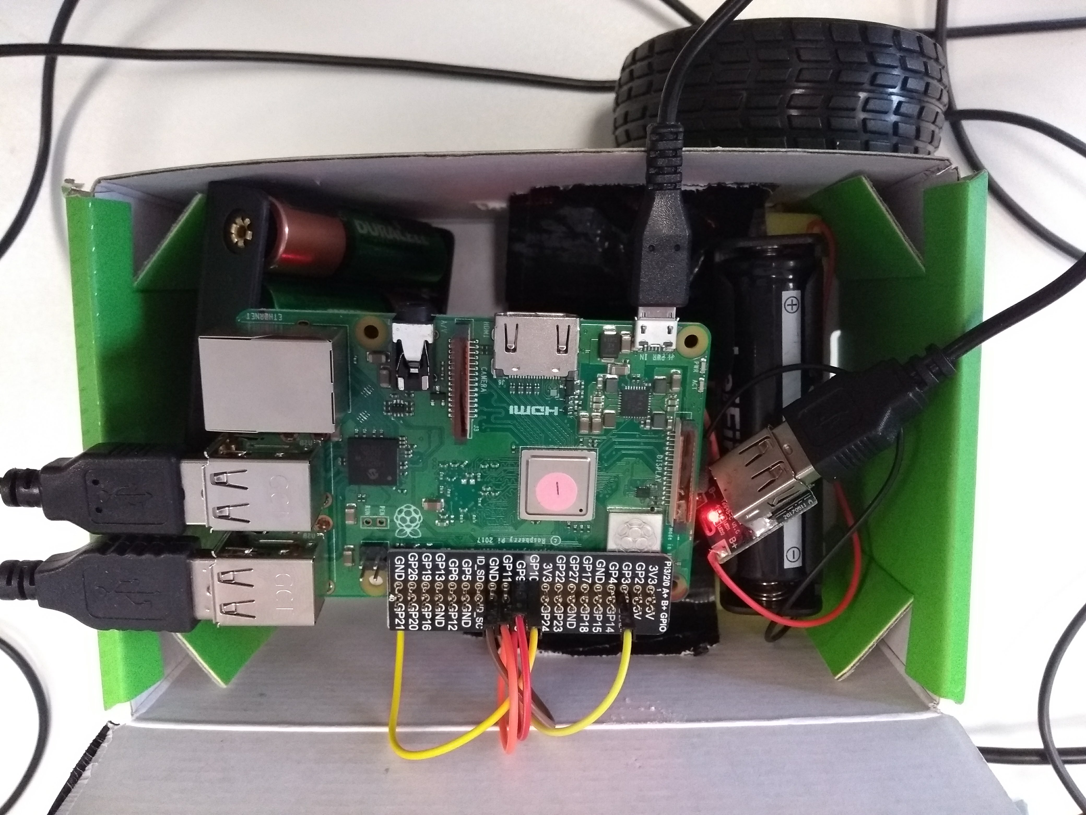
Assemble your robot
There is no “right” way to build your prototype robot chassis, but there are a few things to bear in mind:
- The chassis needs to house the Raspberry Pi, motor controller, and batteries.
- The chassis needs to allow the mounting of a pair of wheels.
- You may want to later add a couple of line sensors, and an ultrasonic distance sensor or a lidar sensor to the chassis.
It’s always a good idea to build a prototype chassis first. Eventually, you can learn how to laser-cut or 3D print a chassis, but in this project, a cardboard box is used as a temporary solution.
The first step is to place your motors into the chassis.
Place your motors inside the box, in roughly the position that you would like them to sit. Then use a pen to mark the place where the motors’ axle will need to pass through the walls of the box. Make sure you are giving your wheels enough room to spin around.
Use a sharp object to poke holes through the sides of the box so that the motors’ axles can fit through.

You will need to fix the motors in place. Use an adhesive putty or tape to hold them down.

Once the motors are in place, you can attach the wheels to the axles.

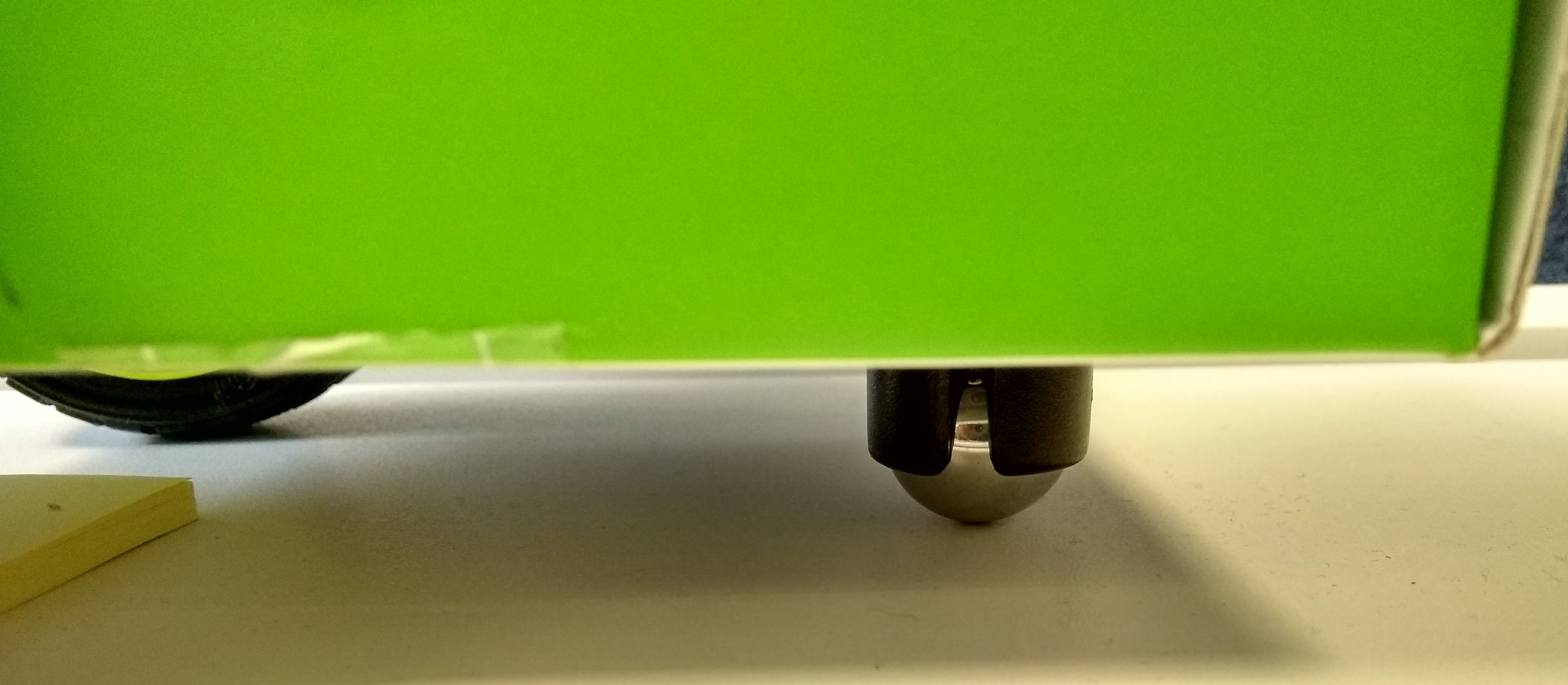
When the wheels are in place, you can screw a ball caster to the front of the container to act as a third wheel.

If you’re using a power bank, you can now power up your Raspberry Pi. If you want to make your own power bank, then follow the guide below.
Make your own power bank
Warning: LiPo batteries can be dangerous, and can cause chemical fires when treated incorrectly. If you have little or no experience handling them, you should use a commercial power bank with safety certification relevant for you locale.
To make your own power bank, you will need a charging protection board, an 18650 battery and an 18650 battery clip.

You will also need access to a soldering iron and some solder.
- Solder the black lead from the battery clip to the negative terminal of the board. Then solder the red lead to the positive terminal.

- Once you’ve soldered the board to the battery clip, insert an 18650 battery. Often the positive and negative terminals are not marked. The smaller metallic terminal is the positive.
The red LED should flash to indicate it is charging.

To use your Raspberry Pi without connecting a mouse, monitor, or keyboard, you can remotely access it via SSH or VNC.
Accessing your Raspberry Pi via SSH
You can access a remote terminal on your Raspberry Pi using the Secure Shell tool (SSH).
SSH is disabled by default on the Raspberry Pi, so you first need to enable it.
- Click on Menu > Preferences > Raspberry Pi Configuration.

- Click on the Interfaces tab. Then check the radio button next to SSH to enable it.

- Click OK to finish.
- To find the IP address of your Raspberry Pi, open a terminal and type:
- hostname -I
- As you have now enabled SSH, it is a good idea to change your password. In a terminal window, type:
- passwd
Now you can access your Raspberry Pi via SSH from another networked computer using the instructions below.
Nix-based operating systems
- If your are using macOS or a Linux-based OS, then SSH is native to the operating system.
- Open a terminal and type the following, replacing 10.10.10.10 with the IP address of your Raspberry Pi.
- ssh pi@10.10.10.10
Type in the password when prompted; it is usually raspberry unless you have changed it.
Chrome OS and Chrome browser
- If you are using Chrome OS or have access to the Chrome browser, then there’s a Chrome app that allows access over SSH. You can find the Secure Shell App in the Chrome Web Store.

- Once installed, click on the app to open it.

- Now you can access the Raspberry Pi by typing in the IP address:

- Then type in the password:

PuTTY (on Windows)
- PuTTY is an app that provides SSH access on Windows.
- Download PuTTY from this site.
- Once installed, open PuTTY from the Start menu and type in the IP address.

- If it’s your first time connecting to this Raspberry Pi, you’ll get a warning dialogue box, so click Yes to connect:

- Then you need to enter the username and password for the Raspberry Pi (usually pi and raspberry, unless you have changed them).

Accessing your Raspberry Pi via VNC
As long as your Raspberry Pi is networked either via WiFi or Ethernet, you can operate it remotely from any existing networked computer.
Virtual Network Computing (VNC) is a protocol that allows you to control one computer from another computer. The advantage of using VNC is that you gain access to the full desktop of the Raspberry Pi, meaning you can use graphical programs from the connected computer.
- The first thing to do is to enable the VNC server on the Raspberry Pi. Raspbian comes pre-installed with RealVNC.
- Click on Menu > Preferences > Raspberry Pi Configuration.

- Enable the VNC server by clicking the respective radio button, and click OK.

You should then see the icon for the VNC server in your menu bar.

Your VNC server will now start whenever the Pi is booted, and will continue to do so until you disable the VNC server again.
To connect to the Raspberry Pi from another computer, follow the instructions in one of the links below.
Connecting with Windows, Linux, or macOS
There are many VNC viewers that can be downloaded and used on your desktop computer. For simplicity’s sake, the instructions below are for using RealVNC.
- Download the client for your preferred operating system from the RealVNC website.
- Install the downloaded software.
- When you run the software for the first time, you will be asked to accept the terms and conditions.
- You can now connect remotely to your Raspberry Pi by typing its IP address into the connection bar. If you don’t know the IP address of your Raspberry Pi, you can find it by clicking on the RealVNC icon on the Raspberry Pi’s desktop.

- Next, you’ll be asked to authenticate. Type in your Raspberry Pi username and password (the defaults are pi and raspberry).

- You should now have a remote desktop session.

VNC with Chrome OS
You’ll need an app from the Chrome Web Store to use VNC on a Chromebook.
- In the Chrome Web Store, search for ‘VNC Viewer for Google Chrome’ and add the application to Chrome.

- With the app open, you can type in the IP address and desktop number for the Raspberry Pi.

- Enter the password at the prompt.

- You should now be connected to the Raspberry Pi.

Other platforms
Most mobile platforms (Android, iOS, Windows Mobile) have their own VNC apps, which are available in the respective app stores.
Challenge: program your robot
You can now write a program to control your robot and make it do any number of things.
Here’s a simple script to make it go in a square shape (you may need to change the sleep functions slightly):
- from gpiozero import Robot
- robot = Robot(left = (7, 8), right = (9, 10))
- while True:
- robot.forward()
- sleep(3)
- robot.stop()
- robot.right()
- sleep(1)
- robot.stop()
Now is your opportunity to program your robot!
Try and complete one of the following challenges:
- Make your robot drive in a perfect circle
- Make your robot drive in a zigzag pattern
- Make a small maze from household objects and program your robot to navigate it
Don’t forget, there are only five basic commands to move your robot:
- robot.forward()
- robot.backward()
- robot.right()
- robot.left()
- robot.stop()
Credits
Raspberry Pi
Our mission is to put the power of computing and digital making into the hands of people all over the world. We do this so that more people are able to harness the power of computing and digital technologies for work, to solve problems that matter to them, and to express themselves creatively.
Related products


Leave your feedback...