


Items used in this project
Hardware components

View all
Software apps and online services
Story
If you would like to purchase on instead of building your own, we sell them on Tindie - https://www.tindie.com/products/29934/
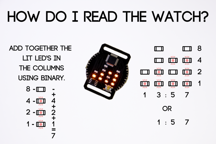
Powered by a CR2032 coin cell battery, this watch tells the time in the best way possible*, Binary!
Press the button on the front, and it will display the time for ten seconds before putting the ATMEGA328 back into deep sleep. Time is kept using an RTC, which can theoretically last for years on a single coin cell. (the LEDS are the biggest drain.)
I was inspired to make these after seeing some other binary watches, and this is my take on it!
Thanks for stopping by!
*If you are a big geek like the best of us :P
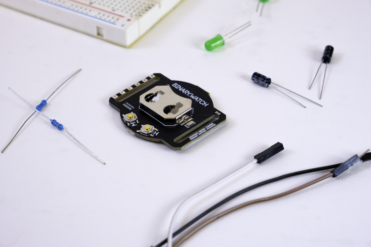
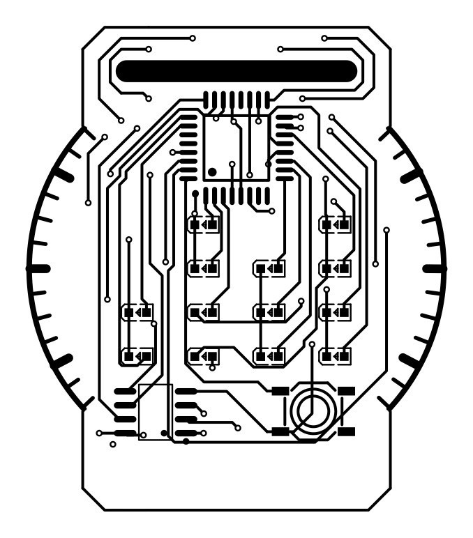
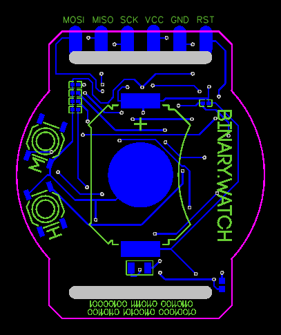
The Binary Watch is actually a fairly simple project to make. The main idea is for the whole thing to be powered by a coin cell, which keeps a RTC ( real time clock ) chip running and keeping time. When the wake pin is connected by the button, the ATMEGA328PB wakes up, reads the current time from the RTC, and displays the time in Binary using the LED's. After ten seconds of no button presses or time changes, the ATMEGA goes back to sleep to save power, and the LED's turn off. There are two buttons on the back, one for hour and one for minutes, and if a press is detected, the RTC will add a minute or hour according to the button. The PCB Layout is fairly simple as well, and can be modified however you like. :) If you would like to make this project, I have included all of Gerber, Pick and Place, BOM, Code, and Schematic files for you. The only tricky part is uploading the code, which is done over ISP using another Arduino. Since that is a project in of itself, I won't go in depth. There is however, a few instructions for uploading in the code file, and other resources are readily available. If you choose to use the ATMEGA328PB (Specifically the PB Version) I would recommend using this board library for Arduino. https://github.com/watterott/ATmega328PB-Testing Here is the pinout for the ISP Pins at the top of the board. Remember to use 3.3 volts if possible. I ordered the PCB's from JLCPCB, which is where I get all my PCB's. Great service, easy, and fairly quick. if you need any help or have any questions, feel free to ask! Thanks! 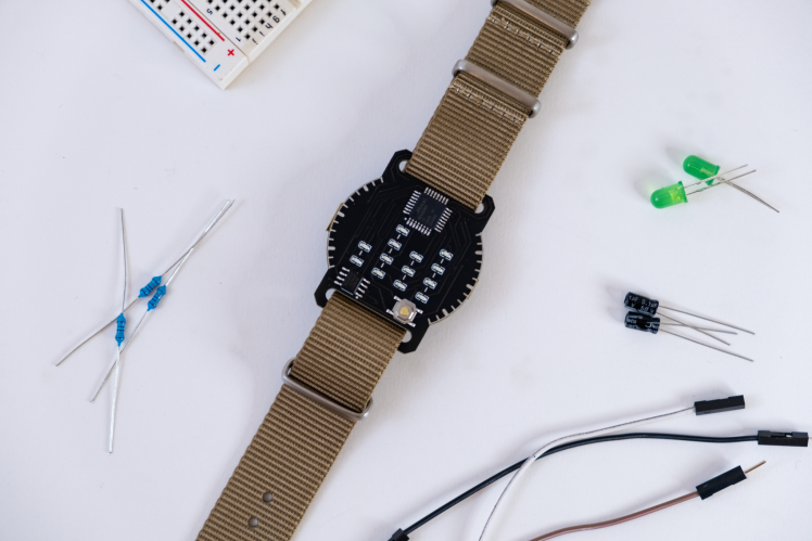
Details
Schematics, diagrams and documents
CAD, enclosures and custom parts
Code
Credits
Related products


Leave your feedback...