
Basic Bass Guitar Amp

Made by electrouser805 / Music
About the project
Let's rock with a DIY bass guitar amplifier, no IoT, no coding, no AI, just pure analog audio like the good old days.
Project info
Difficulty: Moderate
Estimated time: 1 hour
Items used in this project
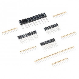
Hardware components


View all
Story
Introduction
Electric Bass Guitar is a solid body musical instrument which has no acoustic cavity (the hollow chamber). Instead, it uses an external audio amplifier (also known as Amp) to amplify the sound. The purpose of this build is to make an upgrade for existing 19 Watt Randall Guitar Amp to a more powerful one without spending too much money.
Features
- 7 Vrms Pre-Amp Output Stage (non-distorted)
- Volume Control down to - 26 dB
- Tone Control (Bass & Treble)
- Gain Control up to 40 dB
- Dual rail +/- 35 Volt power rail for large output swing
- Low Noise Operation
Demonstration
Bass Guitar test 1 In House Guitarist (not me !) is testing the AmpHardware
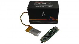
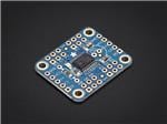
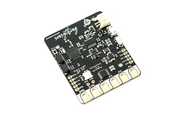
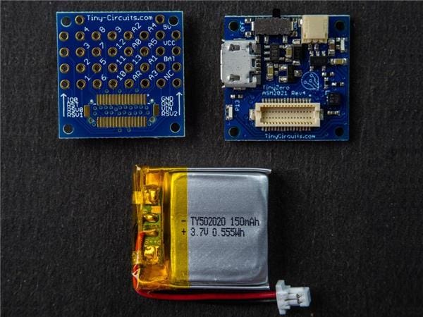
Pre-Amplifier
The pre-amplifier board is connects to the bass guitar's output, buffers the signal, then allows attenuation for volume control. It also enables tone control from user with a Low Pass Filter and a High Pass Filter on the signal chain. Finally, amplifies the audio signal to a stronger voltage level to drive the amplifier stage.
1 / 4 • User Interface for Input, Power, Volume, Tone and Gain controlPower Amplifier
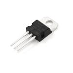
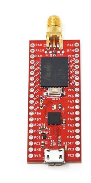
This is the final output stage that drives the 4/8 Ohms speaker build with a TDA7293 100 Watt Amplifier board and a CPU cooler heat-sink and fan combo.
1 / 3 • TDA7293 Amplifier board on CPU cooler heatsinkPower Input Protection & cooling fan protection
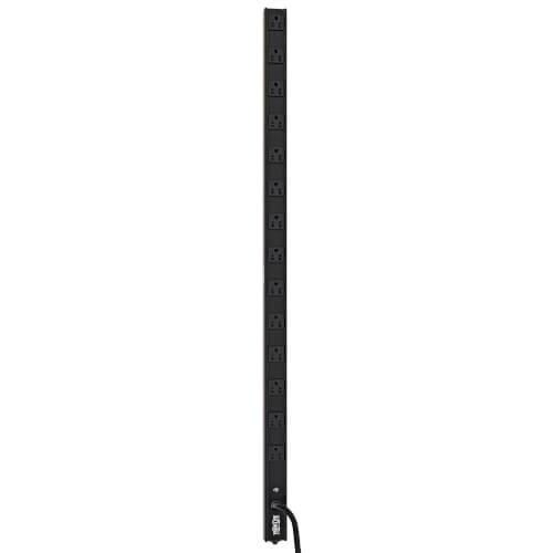
AC power coming from the mains pass through a fuse before going to transformers for protection. A MOV is placed for mains surge protection.
Cooling fan protection is done with a 200 mA Poly fuse and 200 Ohms resistor to drive 12 volts cooling fan from 35 V.
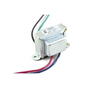
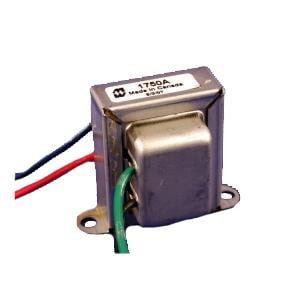
AC supply input protection and cooling fan current limiterDual Rail Power Supply
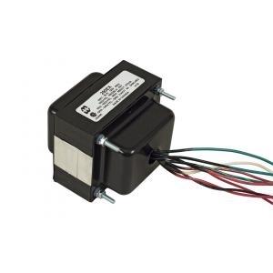
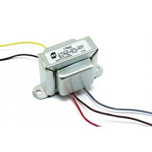
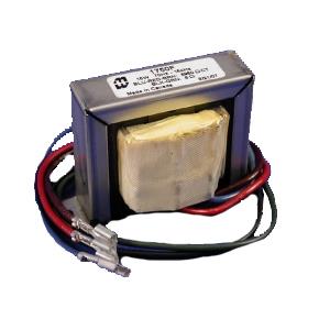
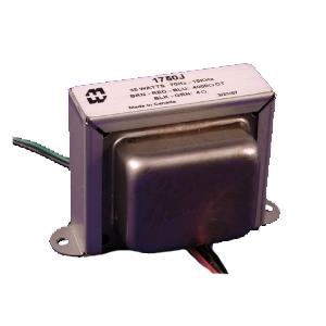
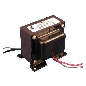
Two transformers of 12-0-12 are used with 2 bridge rectifier to form dual rail power supply. After rectification and filtering the output rails are about +/- 35V to -/+37 V. When fully loaded, it goes down to +/- 32 VDC
1 / 3 • Transformer and Full bridge rectifier 1000uF Ripple filtering capacitors in test setupDC filtering capacitors help smoothing out ripples. Any value from 1000 to 10000 uF can be used. Larger capacitors help getting better dynamic power.
Speaker
Here is the (so claimed 500 Watts sub-woofer) 8 or 10 inch speaker which is mainly designed for low and mid frequency. It's 4 Ohms and has good frequency response from 40 Hz to 5000 Hz
1 / 2 • 10 Inch Sub-woofer Speaker with Zobel networkCircuit Explained
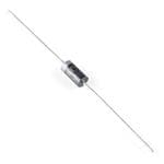
Two separate transformers are used here to generate larger supply rails. There is an input fuse (U2) and a MOV (R9) for short-circuit and surge protection. 2 more fuses (U3, U5) on transformer secondary will provide additional protection. Bridge rectifiers (D2/D3) convert AC to DC, followed by ripple filtering capacitors. Both DC outputs are floating and isolated 35-37 Volts. (-) of top supply and (+) of bottom supply are connected together to make common (Gnd) reference. Thus upper supply is +35 wrt Gnd and lower supply is -35V.
AC to Dual Rail DC Power SupplyTo convert +/- 5 V rails from +/-35 V rails, LM7805 and LM7905 Voltage regulators are used. Since, these voltage regulator can not take more than 25V (abs) in their input, few 5.1 Zener diodes (D5 to D11) are used to reduce the input on voltage regulators near +/-15 Volts. To regulate the zener diodes 10k (R10/R12) are connected to Gnd. Additionally, C13/C14 capacitors are used to stabilize voltages on the input and C21/C22 capacitors on the output of the regulator.
Dual Rail DC Step Down Regulated SupplyNE5532 is powered with regulated +/-5 Volts. One of the opamp inside NE5532 buffers the input signal. C15 is DC blocking capacitor and R13 helps reduce input line noise (at the cost of gain). Output of buffer is connected to a 20k volume pot to attenuate the audio signal as needed. Next, part is the LPF (low pass filter) and HPF (high pass filter) for adjusting tone control. By changing pot R18 and R19, Bass and Treble can be controlled.
Finally the tone adjusted signal goes to the pre-amplifier stage (second opamp) for boosting the voltage level. This stage has a user adjustable 100x gain control from the pot.
Volume, Tone and Gain ControlPre-amplified audio output goes to the TDA7293 board (gain is fixed by design). This board is supplied with the +/-35 Volts power rails, It requires good cooling, so a cpu cooling heatsink with fan is mounted on the chip.
Audio Power Amplifier and CoolingAmplified power output from the TDA7293 board is fed to the 4 Ohms Speaker, R6 and C12 on the speaker forms the Zobel network which helps balancing impedance of the speaker over wide frequency range and shunt out some high frequency noise.
Output SpeakerEnclosure
0.5 x 1 x 2 cubic fit plywood box is used as the enclosure for the amp. This is not the correct size for this amp but it was sitting around for years, thus re purposed.
Enclosure2 Cooling fans are added to keep the transformers, rectifiers, capacitors cool.
PSU coolingAmplifier and Pre amplifier are attached on the top of the enclosure.
(cutting wood is painful without proper tools ! )
Amp and Pre Amp circuitsAdditional Tweaks
- Both Gain and Volume range is reduced by 50% (by paralleling 100k and 22k fixed resistors with variable pots), because too much gain was making the speaker go unstable.
- Added couple of 12V Cooling fans in series to cool the power supply part of the circuit (optional)
- Star Grounding is follow with multiple ground wire from each part.
- 90% of the back side of the box is covered with wooden scale with a vent near the cooling fan
References
Schematics, diagrams and documents
Code
Credits
Related products


Leave your feedback...