
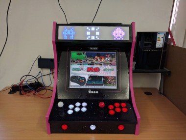
Bartop Arcade Cabinet With Udoo X86
Made by UDOO / Games & Gaming
About the project
Step by step guide to build your own awesome bartop arcade cabinet.
Project info
Difficulty: Difficult
Platforms: UDOO
Estimated time: 2 days
License: GNU General Public License, version 3 or later (GPL3+)
Items used in this project
Hardware components

View all
Hand tools and fabrication machines
Story
In this tutorial, we’re going to see how to make an awesome BarTop Arcade cabinet using UDOO X86. The guide is separated into four different parts:
- The Case (Hardware)
- The Electronic Parts (Hardware)
- The RetroPie (Software)
- The Marquee (Hardware & Software)
Step 1 - The Case
Materials Needed in this part:
- 2x pieces of wood 120cm x 70cm 1,8cm thick,
- Screws;
- T-moulding;
- Primer spray and Black paint spray;
- Vinyl stickers.
To assemble the case of a BarTop Arcade Cabinet, we followed this guide from thegeekpub.com that helped us during the building phase. If you have any doubt during the assembling, please consult it for more detailed info.
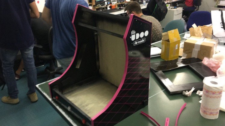
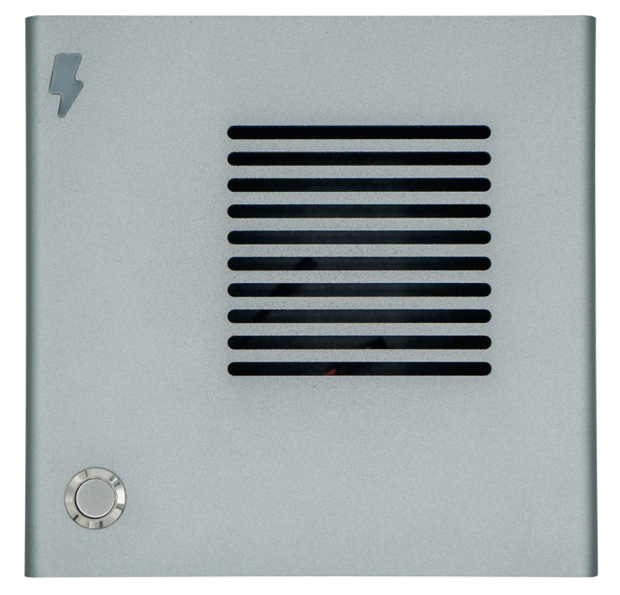
The first thing to do is to create an 80’s retrò looking case of a BarTop Arcade Cabinet.
To create our project, we used two pieces of Plywood 120cm x 70cm, with a thickness of 1,8cm.
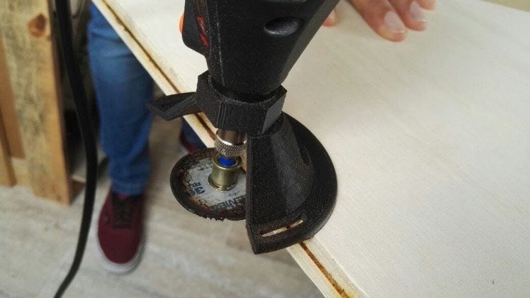
Once we created the cutting layout, we used a laser cutting machine to reproduce the layout onto the pieces of wood. However, you can also use any cutting method that can reproduce the layout, for example, a CNC machine.
Download the UDOO Bartop Arcade Cabinet Wood Cut Plane
Download the UDOO Bartop Arcade Cabinet Stickers Graphics
In the cut plane design, we placed the holes for the buttons and the controllers for the two players, and for the select and player’s start buttons.
The cut plane comes also with some optional holes for the accessories we envisioned, such as: the speakers holes in the plane on the top of the monitor; the external USB connector in one of the side that could be useful to connect wireless keyboard or USB drive; the circular fan hole and the hole for a power switch in the backside.
As an optional step, we routed a groove in the side parts of the case, to allow the affixing of a T-Mold for the perfect retro look!
Once you have all the pieces ready, you need to assemble them.
From the remaining part of the wood, we obtained some strips of different sizes that can help to assemble the cabinet.
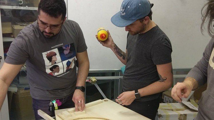
These pieces not only make the assembly of the arcade cabinet easier but has the benefit of leaving no exposed nail heads or screws on the outside of the arcade cabinet.
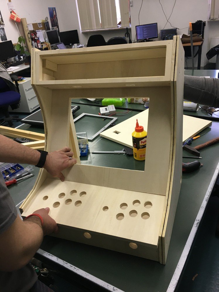
Once we have assembled the cabinet it will look like this:
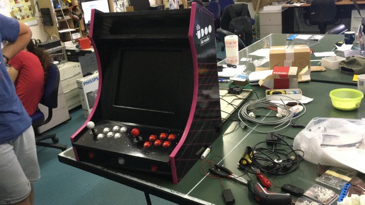
We’ve painted all the part of the Cabinet, first with a primer and then with the black paint to cover all the parts not covered by the vinyl sticker we will apply later.
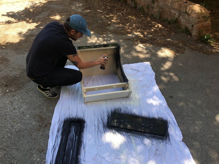
After the painting phase, we pasted the vinyl stickers and the T-Mold with a hammer.
Step 2 - The Electronic Parts (Hardware)
Materials Needed in this part:
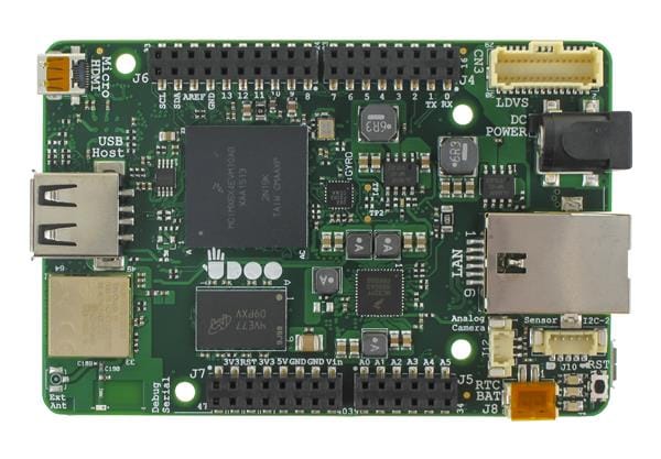
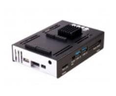
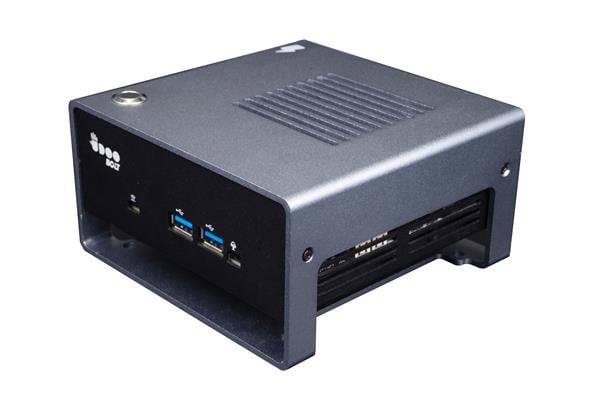
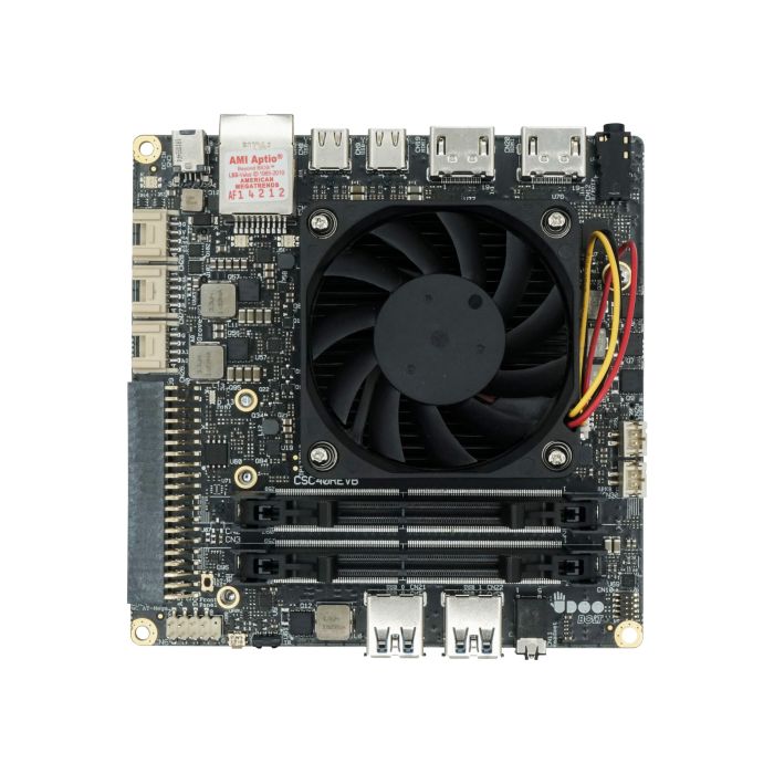
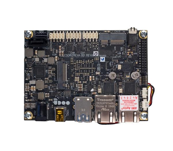
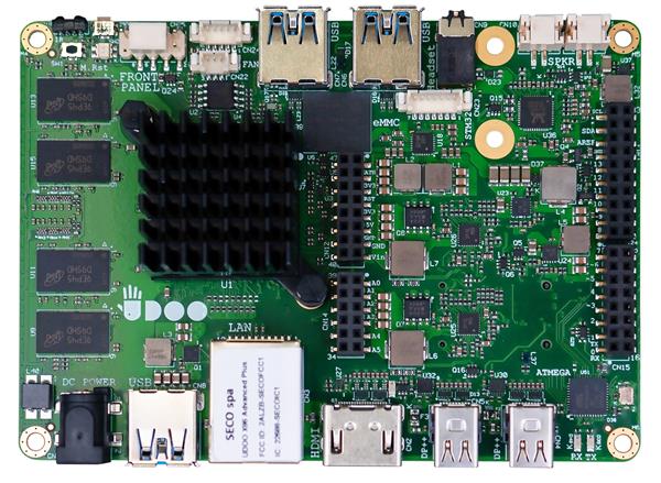
- UDOO X86
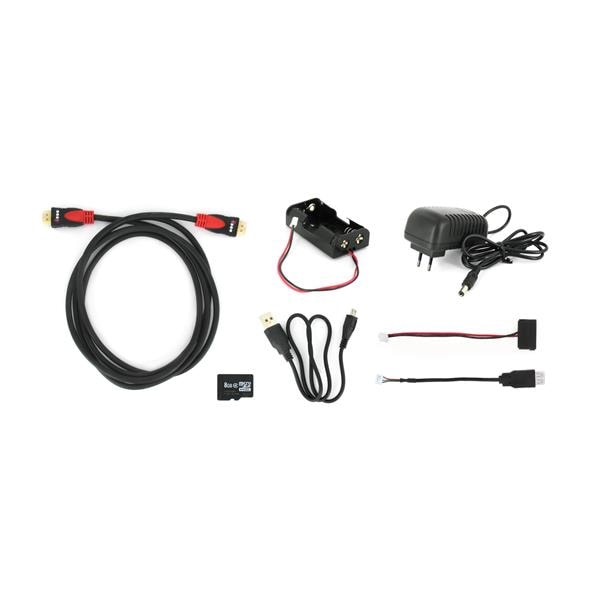
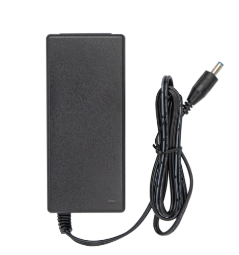
- 12V 3A power adapter
- Acrylic case for UDOO X86
- Monitor. We used a 17inch 4:3 VGA Flat Screen
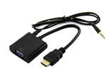
- HDMI-to-VGA adapter
- 2x Arcade Game LED USB Encoder, PC Joystick Kit
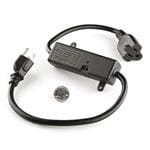
- Multi-plug
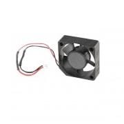
- 12V Fan
- Power Switch
- External USB connector
- 2x speakers 8 ohm
You can create your cabinet with any UDOO X86 versions. All the versions are powerful enough to run all the retro gaming emulators for a great arcade experience. We chose the ULTRA version because we would also run PlayStation 1 and PlayStation 2 games.
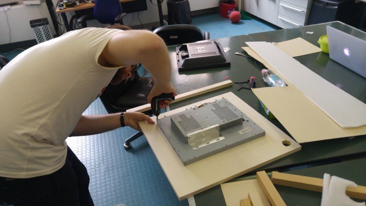
Now that the cabinet case is ready, it is time to install all the major electronic components.
We fixed the monitor to its plane.
We installed the joysticks and buttons for the two players and system, and then we plugged all of these controls into the controller boards. This task is simple because the controller boards connect to the UDOO X86 board by USB and they are directly seen as an input game device.
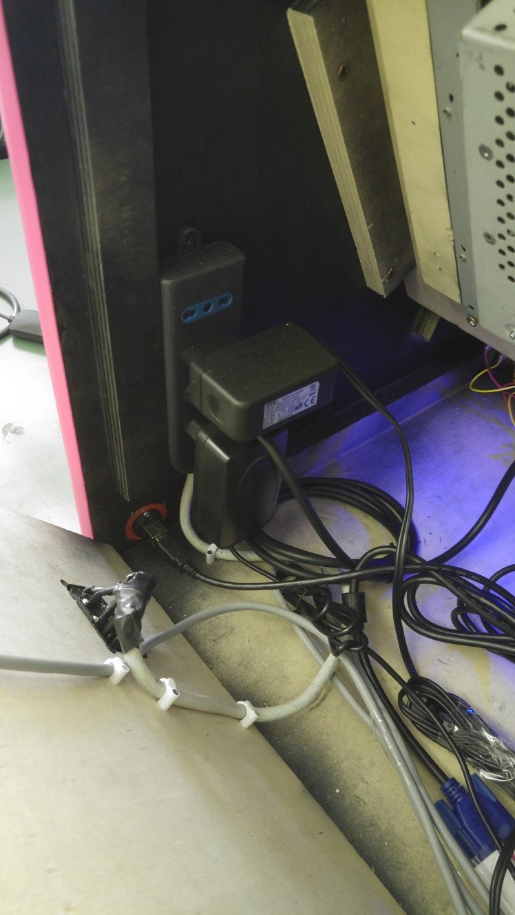
At this point, we set up into the case the multi power plug and the UDOO X86 board.
We’ve connected the controllers via USB and monitor through a DP-to-VGA adapter, and we also installed all the optional accessories:
- Fan connected to the Vin 12V of the Board;
- External USB connected to the spare USB;
- Power switch to the multiple power plug;
- The speakers connected to the speakers connector.
Step 3 - The RetroPie (Software)
Regarding the software, we decided to install Retropie on top of Ubuntu 16.04, to have an outstanding retro-gaming experience possible.
RetroPie can be thought of as a framework which provides facilities for emulator launch and control, along with the configuration of standard features such as screen resolutions and controller setup.
One of the software wrapped by RetroPie is EmulationStation, a graphical front-end allowing selection of video game system emulators and games.
We followed the official RetroPie guide to install and configure it https://github.com/retropie/retropie-setup/wiki/Debian
Materials Needed in this part:
- Ubuntu 16.04;
- Retropie.
First of all, you need to setup your UDOO X86 and install Ubuntu on it as described in the Getting Started with UDOO X86 page.
All the accessories used works out-of-the-box with UDOO X86 without installing any drivers. For example, the player’s controllers and buttons connected through USB are seen as a gamepad (DragonRise Inc. Gamepad) from Linux and directly configurable in a straightforward way by the RetroPie settings.
Step 4 - The Marquee (Hardware & Software)
Materials Needed in this part:
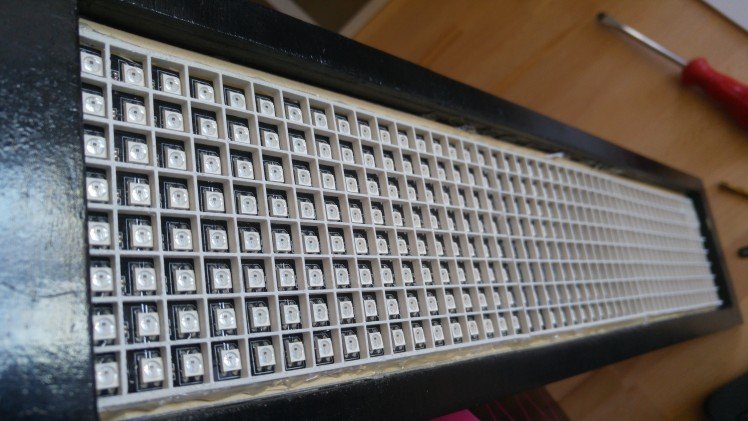
- 2x Flexible RGB LED Matrix 8x32 WS2812B 5V;
- 5V 3A power adapter.
One of the cool features of UDOO X86 is that it embeds an Arduino 101 microcontroller that can be used to control the real physical environment.
We exploit the Arduino capabilities to control two RGB LED Matrix WS2812B to create a beautiful retro animated Marquee.
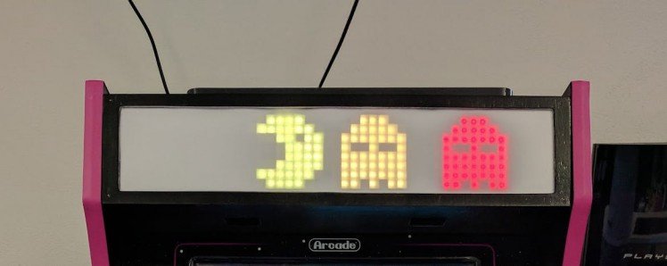
Since the size of the marquee, we used two matrices connected to cover the space with an 8x47 matrix. The matrices have a simple connector on the back to make they work in cascade.
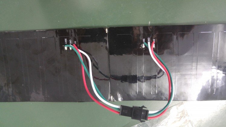
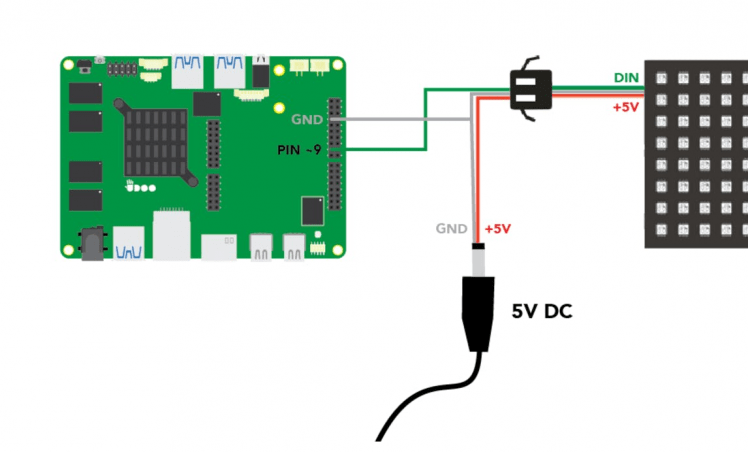
The matrix composed needs only 3 Pin to be connected to the power source and the Arduino 101 pinout of the UDOO X86. The 5V power source for the LED matrix could be provided directly by the pinout of the UDOO X86, but since the power consumption of the entire matrix is quite high, we preferred to use an external power supply.
Below you can find an image that shows how to connect the matrix to the UDOO X86 pinout. The Data Pin (DIN) of the matrix need to be connected to the Pin 9 (PWM) of the Arduino 101 accordingly to the Arduino sketch. The 5V Pin of the matrix need to be connected to the 5V (+) provided by the power supply, and the GND need to be connected to the negative pole (-) of the power supply and the GND of the Arduino pinout.
Once the matrix is connected we can take care of the software.
You need to install the Arduino IDE to program the Arduino 101 side of the UDOO X86.
You can check the UDOO X86 docs. to
setup the system and install the Arduino 101 board manager support.You also need to install some libraries.
To control the WS2812B LED Matrix. The libraries required are:
- Adafruit_NeoPixel
- Adafruit_NeoMatrix
- Adafruit_GFX
This is the sketch we used to create some cool 8bit retro-gaming animation.
https://github.com/UDOOboard/UDOOCabinet_NeoMatrix_LED_Markee
Once uploaded the sketch the animation will start on the Marquee matrix.
To create a more defined pixel effect we 3d printed a grid to surround each pixel and covered all the matrix with opaque plexiglass.
Here you can find some useful guides to understand better how to use the RGB LED matrix with Arduino:
https://learn.adafruit.com/adafruit-neopixel-uberguide/neopixel-matrices
https://learn.adafruit.com/adafruit-neopixel-uberguide/neomatrix-library
http://www.instructables.com/id/Getting-Started-With-NeoPixle-WS2812-RGB-LED/
Credits
Related products

Leave your feedback...