
Automatic irrigation and plant watering system

Made by rau7han
About the project
The watering system using Arduino and soil moisture sensor. Also, we can control the water supply automatically through this system.
Items used in this project
Hardware components

Story
In this project, we will build an automatic plant watering system using a soil moisture sensor and Arduino. The soil moisture sensor will be used to measure the moisture level in the soil and the Arduino will be used to control the watering system.
Required material- Arduino Nano* 1
- Soil Moisture sensor * 1
- 5v relay module * 1
- Mini water pump with small pipe * 1
- Connecting wires
- 16x2 LCD
In this project, we employ the use of a Moisture sensor to monitor and maintain the optimal moisture levels for your plants. With this automated system, you can bid farewell to worries about plant survival during your absence. It's equally suitable for both outdoor gardens and indoor plants, allowing you to care for your leafy companions wherever they may be.
Working of the Automatic Irrigation System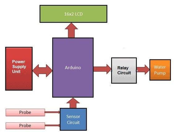
The Automatic Irrigation System with Arduino works by using a moisture sensor to detect the moisture level in the soil. The Arduino Uno microcontroller is programmed to read the sensor's values and activate a water pump when the moisture falls below a predetermined threshold.
- Power on: The system is powered by a 12V power supply connected to the Arduino board. The power supply is regulated using a voltage regulator to provide stable 9V DC power to the Arduino Nano.
- Sensor reading: The system uses a capacitive soil moisture sensor connected to an analog input pin of the Arduino.
- Moisture calculation: The analog value from the sensor is mapped to a moisture percentage using predefined thresholds for air value and water value.
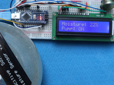
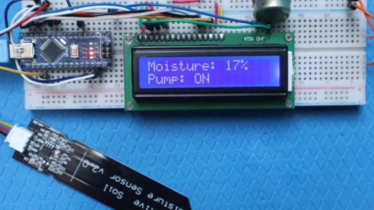
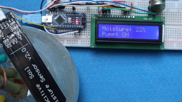
- LCD display: The moisture percentage is displayed on a 16x2 LCD module connected to the Arduino.
- Relay control: Based on the moisture percentage, the Arduino makes a decision whether to turn on or off the irrigation system. If the moisture percentage is below 30.0, indicating a low moisture level, the Arduino sets the relay pin to LOW, turning on the relay connected to the pump. This activates the pump and starts the irrigation process.
- Pump status display: The LCD module displays the status of the pump on the second line. If the pump is turned on, it shows "Pump: ON". If the moisture percentage is above 70.0, indicating sufficient moisture, the Arduino sets the relay pin to HIGH, turning off the relay and indicating that the pump should be off. The LCD displays "Pump: OFF" in this case.
- Monitoring and loop: The Arduino continuously reads the moisture level, updates the LCD display, and checks the moisture percentage to determine the pump status.
The water pump then delivers water to the plants until the moisture level reaches the selected threshold again. This automated process provides that plants receive the right amount of water, even when the owner is away, boosting their health and vitality
Soil Moisture Sensor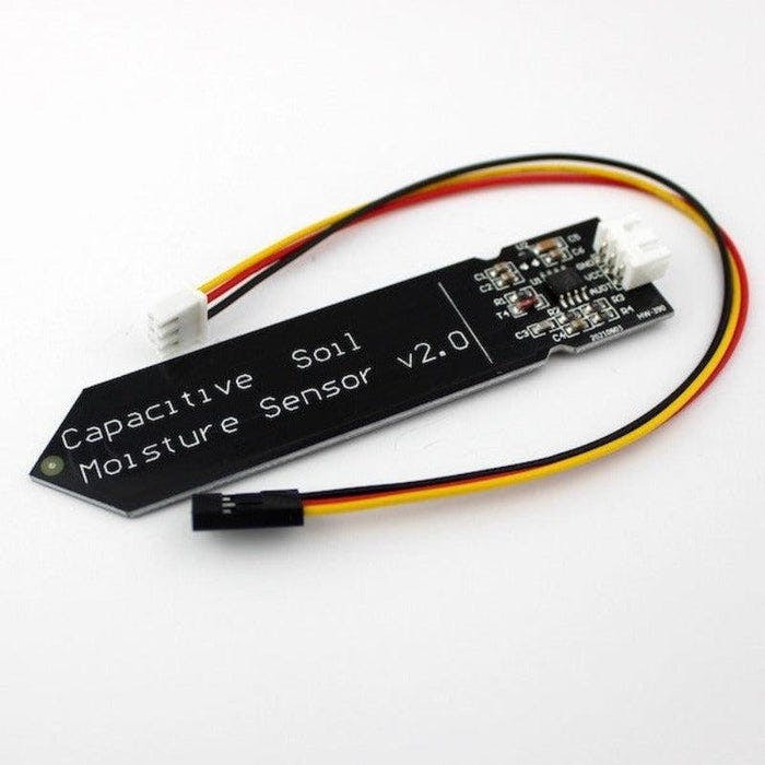
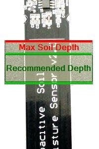
A soil moisture sensor is a device that measures the moisture content in the soil. It detects the electrical conductivity or resistance of the ground, which varies with moisture levels. The sensor is calibrated to determine a moisture threshold for watering. When the moisture falls below this threshold, it signals the need for watering.
This information is typically integrated with an Arduino, which activates the irrigation system to provide water to the plants. Continuous monitoring ensures the plants receive optimal hydration, preventing under or overwatering.
This module includes an integrated voltage regulator providing it with an operating voltage range of 3.3 ~ 5.5V. It is perfect for low-voltage microcontrollers, both 3.3V and 5V. For compatibility with Raspberry Pi, an ADC adapter is required.
Specifications & Features- Operating Voltage: 3.3 ~ 5.5 VDC.
- Operating Current: 5mA.
- Interface: PH2.54-3P.
- Dimensions mm(LxWxH): 98 x 23 x 4.
- Supports 3-Pin Gravity Sensor interface
- Analog output.
- Weight (gm): 15.
- Garden plants
- Moisture detection
- Intelligent agriculture
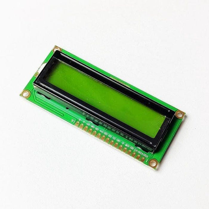
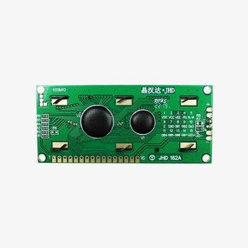
16x2 LCD is a display module with 16 columns and 2 rows, capable of displaying 32 characters. It utilizes liquid crystal technology and often includes a backlight for visibility in different lighting conditions.
The LCD module interfaces with external devices and is commonly used for character-based information display in various applications.
Specifications & Features- I2C adapter allows flexibility in connections
- I2C Reduces the overall wiring.
- 16 characters wide, 2 rows
- White text on the Blue background
- The single LED backlight
- Character Color: White
- Backlight: Green
- Supply voltage: 5V

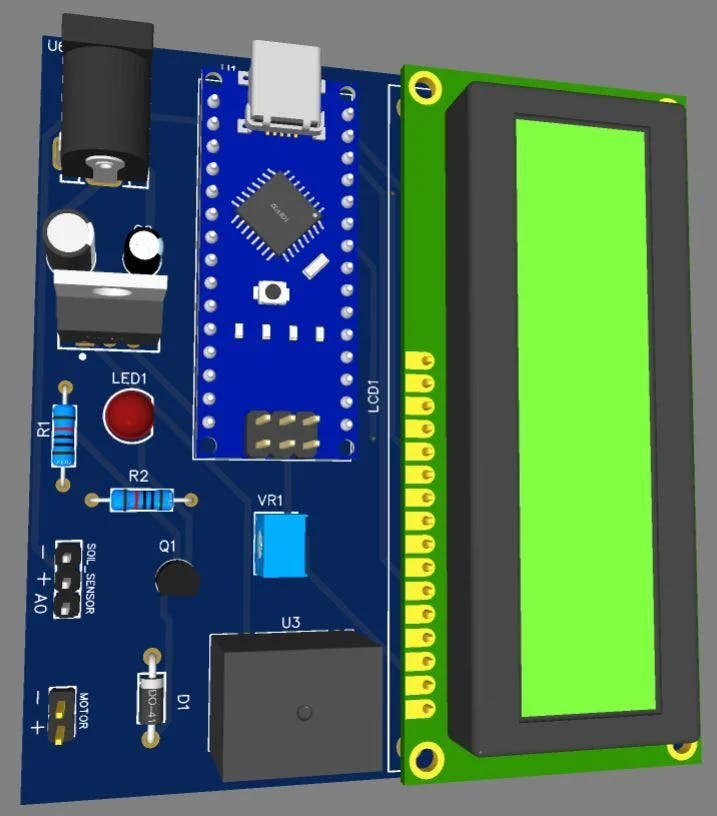
The device is powered by a 12V power supply unit using a 12V DC power adapter connected to the power jack. The reason for using a 12V power supply is that both the relay and motor require a 12V power source. To regulate the voltage, a 7809 Voltage Regulator IC is used. The 7809 IC converts the 12V DC input to a stable 9V DC output.
To ensure a smooth voltage supply, two electrolytic capacitors (10uF and 1uF) are connected at the input and output of the regulator IC. The 9V DC output from the regulator is then connected to the Vin pin of the Arduino Nano board.
By using the 7809 IC, the voltage is regulated and avoids excessive heating that would occur if the 12V was directly applied to the Arduino's Vin pin due to the large dropout voltage.
PCB Design, Gerber File - PCBwayIf you don’t want to assemble the circuit on a zero PCB or a breadboard and you want PCB for the project, then here is the PCB for you. I used EasyEDA to draw the schematic first.
The Gerber File for the PCB is given below. You can simply download the Gerber File and order the PCB from PCBway at an affordable price.
You can use this Gerber file to order high-quality PCB for this project. To do that visit the PCBway official website by clicking here: https://www.pcbway.com/
Why PCBway
- Most Efficient, Economic, Innovative PCB Solutions
- Higher Quality
- Lower Cost
- Faster Delivery
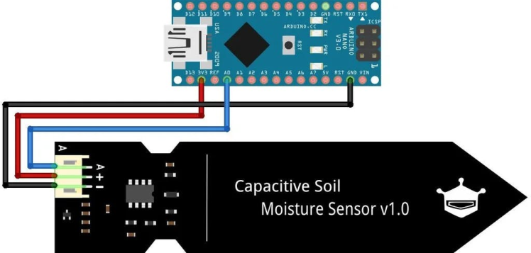
Capacitive Soil Moisture Sensor With Arduino board
- Connect the VCC pin of the soil moisture sensor to the 3.3V pin of the Arduino.
- Connect the GND pin of the soil moisture sensor to the GND (ground) pin of the Arduino.
- Connect the Aout pin of the soil moisture sensor to the A0 analog input pin of the Arduino.
LCD (Liquid Crystal Display) With Arduino Board
- Pin 1 (VSS), Pin 5 (R/W), and Pin 7 (LED-) of the LCD module are connected to the GND (ground) of the Arduino Nano. This establishes the common ground reference.
- Pin 2 (VDD) and Pin 15 (LED+) of the LCD module are connected to the 5V pin of the Arduino Nano. These pins provide the power supply for the LCD module and the backlight.
- The LCD module's Pin 3 (VO) is connected to a 10K potentiometer (variable resistor). This allows you to adjust the LCD's contrast by varying the voltage applied to Pin 3.
- The control pins of the LCD module are connected to specific digital pins of the Arduino Nano:
- Pin 4 (RS) of the LCD module is connected to digital pin 12 of the Arduino Nano.
- Pin 6 (E) of the LCD module is connected to digital pin 11 of the Arduino Nano.
- Pin 11 (D4) of the LCD module is connected to digital pin 10 of the Arduino Nano.
- Pin 12 (D5) of the LCD module is connected to digital pin 9 of the Arduino Nano.
- Pin 13 (D6) of the LCD module is connected to digital pin 8 of the Arduino Nano.
- Pin 14 (D7) of the LCD module is connected to digital pin 7 of the Arduino Nano.
- In this project, digital pin D2 of the Arduino Nano is used to control the relay. It is connected to the control pin of the relay module, allowing the Arduino to turn the relay on or off.
Remember to adjust the pin connections and adjust your code accordingly if you decide to use different digital pins for the LCD control or the relay control.
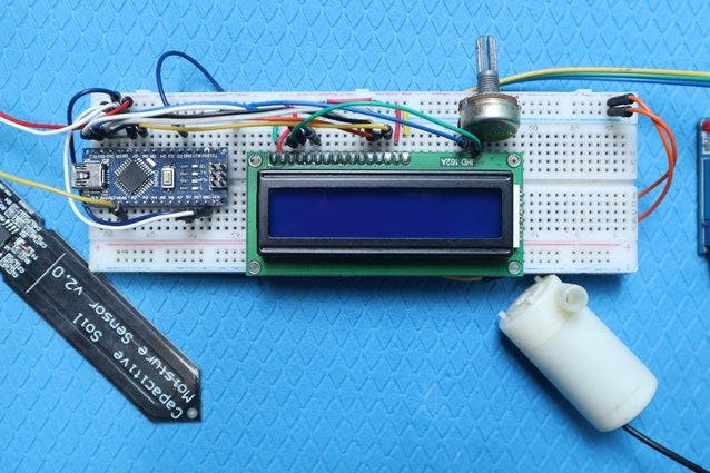
Breadboard Assemble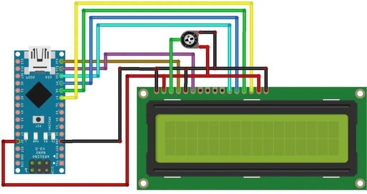
Assemble the Automatic Irrigation System on a breadboard:
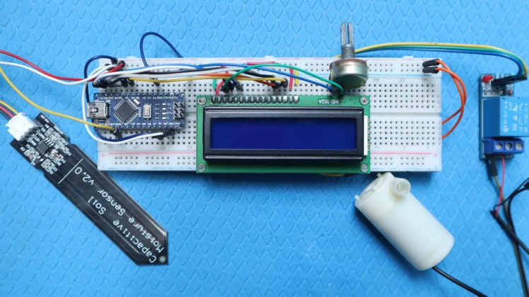
Upload the code to the Arduino Nano using the Arduino IDE.
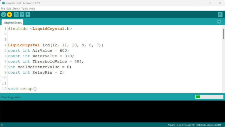
#include <LiquidCrystal.h>


LiquidCrystal lcd(12, 11, 10, 9, 8, 7);
const int AirValue = 600;
const int WaterValue = 310;
const int ThresholdValue = 484;
int soilMoistureValue = 0;
const int RelayPin = 2;


void setup()
{
  Serial.begin(9600);
  lcd.begin(16, 2);
  pinMode(RelayPin, OUTPUT);
  digitalWrite(RelayPin, HIGH);
}


void loop()
{
  soilMoistureValue = analogRead(A0);
  Serial.println(soilMoistureValue);


  lcd.setCursor(0, 0);
  lcd.print("Moisture: ");
  float moisturePercentage = map(soilMoistureValue, AirValue, WaterValue, 0, 100);
  lcd.print(moisturePercentage, 0);
  lcd.print("%");


  int upperLimit = ThresholdValue + 0.1 * (AirValue - WaterValue);
  int lowerLimit = ThresholdValue - 0.1 * (AirValue - WaterValue);


  if (moisturePercentage < 30.0)
  {
    digitalWrite(RelayPin, LOW);
    lcd.setCursor(0, 1);
    lcd.print("Pump: ON ");
  }
  else if (moisturePercentage > 70.0)
  {
    digitalWrite(RelayPin, HIGH);
    lcd.setCursor(0, 1);
    lcd.print("Pump: OFF");
  }
  else
  {
    lcd.setCursor(0, 1);
    lcd.print("Pump: ");
    if (digitalRead(RelayPin) == LOW)
    {
      lcd.print("ON");
    }
    else
    {
      lcd.print("OFF");
    }
  }


  delay(250);
  lcd.clear();
}
This code uses the LiquidCrystal library to control an LCD module connected to Arduino pins 12, 11, 10, 9, 8, and 7.
The code reads the analog value from the soil moisture sensor connected to analog pin A0. Based on the moisture reading, it calculates the moisture percentage and displays it on the LCD.
Working...The code defines three threshold values: AirValue, WaterValue, and ThresholdValue, which are used to determine moisture levels. I
If the moisture percentage is below 30.0, the relay connected to pin 2 is turned on, indicating that the pump should be ON.

If the moisture percentage is above 70.0, the relay is turned off, indicating that the pump should be OFF. Otherwise, the code checks the current state of the relay and displays it on the LCD.
Schematics, diagrams and documents
Code
Credits
Related products


Leave your feedback...