
Arduino Negative Voltmeter

Made by electrouser805
About the project
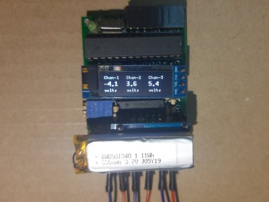
3-channel voltmeter with the ability to measure both negative & positive voltages on the same circuit or 3 different circuits simultaneously
Project info
Difficulty: Easy
Platforms: Arduino
Estimated time: 1 hour
License: GNU General Public License, version 3 or later (GPL3+)
Items used in this project
Hardware components

View all
Story
Stuck with only one multimeter/voltmeter ? But, sometimes you need to check 2 or 3 voltages as the same time. Then this is something you might consider making, a real DC voltmeter !
Designed with commonly available components and easy to understand code, can measure both positive and negative voltages simultaneously on 3 nodes in a single circuit or 3 separate circuits.
Demonstration Measuring voltages across resistor and battery on 2 different circuits HardwareFollowing hardware are used to build this device:-
- Arduino Uno: Uploading code on the ATmega328P microcontroller
- ATmega328P: 8-bit micro with Arduino Bootloader and built-in 10 bit ADC
- 128x32 1306 OLED Display with I2C interface: Display Voltages
- LM324 OpAmp: Analog signal conditioning for ADC
- 4cm x 6 cm FR4 protoboard: Circuit board for the build
- 10k multiturn pot: Adjusting zero (half AREF) voltage
- TP4056 module: LiPo battery charging
- LiPo battery: 300mAh rechargable battery to power the device
Hardware

Hardware
Working Principle: AFE ExplainedNormally, ATmega328P (Arduino Uno) can measure voltages between Gnd and AVCC range (i.e. 0 to 5V) without any voltage divider resistors network. If internal AREF is enable, it can measure voltages between Gnd and AREF range (i.e. 0 to 1.1 V). With some voltage divider, it is possible to measure higher voltages than 5V. These are all positive voltages with respect to Gnd.
But it can not measure any voltages below Gnd, meaning it can't measure negative voltages. The problem is that, ATmega328P has a single ended ADC, which by default makes measurement with respect Gnd.
The solution is, don't make measurement with respect to Gnd anymore.
Real voltmeters have COM (Black) and V(Red) terminals, you connect COM to one node, V to another node on a circuit. The voltage reads on V node with respect to COM node.
You need to build an (AFE) Analog Front End, some sort of signal conditioning circuit to generate a COM like behavior. This COM node should have a voltage somewhere in between AVCC and Gnd. Ideally, half AVCC volts.
Take external voltage measurements with respect to COM, you can easily measure both positive and negative voltages !
Please check the following circuit carefully :
Differential measurement with 2 single ended ADC channels

Differential measurement with 2 single ended ADC channels
So, what's happening here ? Internal reference AREF is enabled on ATmega328P (from firmware). AREF pin has 1.1 V. Now, ADC measurement has an effective range of 0 to 1.1 volts.
Next, using a LM324 Opamp this 1.1 AREF voltage is buffered, meaning we still have 1.1 voltage from the first Opamp's output. A 10k multiturn trim pot is set exactly to 5k to produce 550mV (half AREF) volts. This 550 mV signal is buffered with the second Opamp. 550 mV signal is also connected to ADC Ch - 0. It should read 512 (half of 10 bit).
There is a voltage divider network consist of 5 Mega Ohms (two 10M in parallel) and 100 Kilo Ohms resistor, which is connected to the output of second Opamp.
I am defining, lower resistor end (100k) as COM and higher resistor (5M) end as V on this voltage divider network. The mid point of this divider is connected to ADC Ch - 1. When no external voltage is applied to this divider, ADC Ch - 1 should read 512 (because of 550 mV)
When an external voltage is applied, the voltage divider mid point voltage will shift above or below 550 mV. If external voltage on V is higher (positive voltage) with respect to COM, it will shift above 550 mV, If external voltage on V is lower (negative voltage) with respect to COM, it will shift below 550 mV. The ADC Ch - 1 reading will change accordingly. Using this change in ADC reading we can calculate external voltages.
Why use AREF instead of AVCC ?
This design is LiPo battery powered, a full charge LiPo will start from 4.2 Volts and gradually the voltage will drop. So, AVCC will also change. But internal reference AREF has constant 1.1 Volts. That's why I chose AREF.
If other microcontrollers are used, which do not have AREF, you can use TL431 IC to generate reference voltage !
Why use LM324 Opamp ?
LM324 IC has 4 Opamps in a single package, widely available and it's output can go (very close) to Gnd. It also works with any supply voltage between 3 to 32 volts.
You can always use better Opamps (Precision, Low Noise, Rail-to-Rail)
Voltage Calculation FormulaMeasured voltage with ADC will be a tiny fraction of actual voltage applied. That's why following formula is used inside the firmware to calculate back the actual voltage:-
Formula

Formula
Voltage Divider Resistor: Range vs Resolution- Selecting the right input resistor R_Low and R_High is important because the values of resistors will determine the effective voltage measurement range based on this formula :
+/- V = (R_High / R_Low) / 2
- R_High and R_Low must have a watt rating which can handle the measurement voltage, should satisfy following formula :
V < sqrt ((R_High + R_Low) * P)
- Input impedance of a voltage measurement device must be in the order of hundreds of Kilo Ohms to few Mega Ohms to minimize the loading effect :
R_High + R_Low > hundreds of kOhms to few MOhms
For this project, this voltmeter can measure +/- 25 volts with R_High = 5M (or 5000k) and R_Low = 100K with 1/10 watt rating, which satisfy above 3 conditions
- Next comes measurement resolution which is limited by actual ADC resolution and the effective measurement range you want to set. ADC resolution is the smallest incremental voltage that can be recognized.
Measurement Resolution = Measurement Range / ADC Resolution
- For example : If the measurement range is set +/- 5 V with 10 bit ADC, you should get a resolution of about 10 mV in that range. But for this design with +/- 25 V of measurement range (of total 50V), resolution is about 49 mV.
- Resolution also depends on how many digits are shown in the display. This design only shows 1 digit after decimal point, so 49 mV resolution could be as high as 100 mV or 0.1 volt.
Example : Suppose a fresh AA battery reads 1.627 volts with a Fluke voltmeter, but this voltmeter may read only 1.5 or 1.6 or 1.7 volts
For better range or resolution select microcontroller with 12 bit ADC or moreReduce measurement range to increase resolutionReduce resolution to increase range or measure bigger voltages
Accuracy depends on many things. Some of the following tips are implemented in this project.
- First of all, input resistors (resistors on voltage divider R_Low and R_High) must have better tolerance in the order of 1% or less. This will make sure the resistors have resistance very close to their rated value.
- Stable power source (preferably battery, no SMPS) with decoupling capacitors on the AVCC and Gnd pin will reduce noise. 10uF cap is recommended
- Stable AREF or Analog Reference Voltage is very important for accuracy, putting a 100nF cap will do that.
- Using low noise electronics will help improve accuracy (better Opamp)
- Good routing practice and Shielding on Analog Front End is recommended
Implementing following action in firmware will improve accuracy :-
- Adding slight delay before/after switching analog channels
- Discarding the first analog conversion value
- Taking few hundred samples and average those to improve accuracy
- Using offset variables for soft correction/adjustment of readings
Although the AREF pin of Arduino UNO or Atmega328P can be set to 1.1 volts with following code
analogReference(INTERNAL);The actual AREF voltage may vary between 1.06 volts to 1.13 volts from chip to chip. It is recommended to measure AREF pin with a high accuracy multimeter and find the actual voltage. Then define that in code for better accuracy
#define AREF 1.097 // Aref pin voltageDon't just copy paste 1.1 volt !
Input Protection: Safety Matters !This is the bi-directional diode clamping for over voltage or surge protection you may use in parallel to R_Low. I left this part in my build due to lack of space !
Bi-directional voltage clamp

Bi-directional voltage clamp
Safety should never be taken lightly ! These diodes will start to clamp when the voltage across R_Low exceeds +/- 800 mV. This is just an example, use different diode types for a suitable clamping voltage as needed.
Programming & Soldering- Step 1: Download and Install Arduino from here on your computer.
Download IDE

Download IDE
- Step 2: Open the IDE. Go to Tools > Library Manager and type 'u8g'
Installing u8g library

Installing u8g library
install the u8glib (by Oliver) library for 1306 OLED display.
- Step 3: Connect Arduino Uno to USB, copy and paste the code attached below. Then compile and upload the code.
- Step 4: Remove the Atmega328P chip from Uno board
Remove Atmega328 after uploading code

Remove Atmega328 after uploading code
- Step 5: Build a circuit according to this schematic. Solder all the components on a protoboard.
1 / 3 • Voltmeter Schematic

Voltmeter Schematic

Complete Build of the Voltmeter based on the schematic

Soldering
Performing Voltage Calibration & MeasurementsCalibration
For best results, you need to calibrate this voltmeter with a regular multimeter/voltmeter. You will need any battery AA or LiPo. Measure the voltage of the battery with regular meter. Then measure that battery with this voltmeter. See some discrepancy in reading, now slightly trim/adjust the 10K pot (see schematic) to calibrate.
Do the same procedure by reversing the battery for negative voltage.
You can also do soft-calibration from code by adding/subtracting some offset value with the resistors defined values.
Measurement
There are 3 Commons COM1, COM2, COM3 and 3 corresponding V1, V2, V3 probes for voltage measurement on 3 different channels.
For channel 1, voltage is measures on V1 with respect to COM1. If a circuit node probed with V1 has higher potential than a node probed with COM1, voltage reading will be positive. If both V1 and COM1 are swapped on those two circuit nodes, voltage reading will be negative.
Same goes for channel 2 with V2 & COM2 and for channel 3 with V3 & COM3.
When measuring three different voltages on 3 different circuits which don't share any electrical connections, use V1/COM1, V2/COM2, V3/COM3 pairs for 3 circuits.
3 different voltage measurements on 3 different circuits

3 different voltage measurements on 3 different circuits
When measuring three different voltages on a single circuit, DO NOT USE multiple COMs. Just connect ONLY ONE COM (for example just COM3, any COM will do !) to the Gnd or any node of that circuit. Then use V1, V2, V3 to measure 3 different voltages on 3 different nodes with respect to the Gnd or node where COM is connected.
3 different voltage measurements on single circuit

3 different voltage measurements on single circuit
Connecting multiple COMs on same circuit will screw up readings !
Conclusion & Future WorksI forgot to add something important, showing OL (Over Load) when voltage range exceeds measurement range. Hopefully, I will update the code with extra features.
Some voltage logging on the internal EEPROM could be handy, I will try to do that too. I want to add couple of buttons for REL (zeroing ghost voltage) and HOLD (freezing screen). I have already soldered a female header on the top for future extensions, stay tuned.
This design can be used to measure slow changing AC voltages/signals (assuming sinusoidal) without any change in hardware. It can also be used to design Shunt Ammeter (hint: replace voltage divider with very low value R). But you need to write a different code for that.
This concept will work with any microcontroller, feel free to build your own design and good luck.
Schematics, diagrams and documents
Code
Credits
Related products


Leave your feedback...