
Arduino Nano And Visuino: Animate The Colors Of Rgb Led

About the project
Programming RGB LED Modules to show changing colors is an easy way to improve your mood, and thanks to Visuino it has never been easier.
Project info
Difficulty: Easy
Estimated time: 1 hour
License: GNU General Public License, version 3 or later (GPL3+)
Items used in this project

Software apps and online services
Story
Programming RGB LED Modules to show changing colors is an easy way to improve your mood, and lighten your evenings. Programming Arduino to do the animations however can be challenging. With Visuino however you can create great effects in matter of couple of minutes or less.
In this tutorial I will show you how easy it is to connect RGB LED Module to Arduino Nano and program it with Visuino to animate the colors.
I have also made Video Tutorial of this project.
Step 1: Components
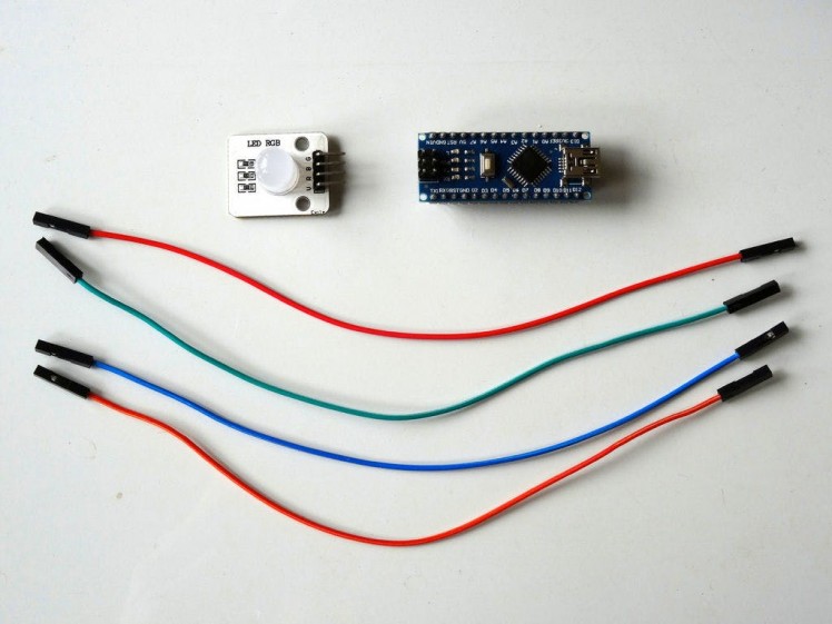
- One Arduino compatible board (I use Arduino Nano, because I have one, but any other will be just fine)
- One RGB LED module (I got my one from Makerfabs).
- 4 Female-Female jumper wires
1 / 4 • Picture 1

Picture 1

Picture 2

Picture 3

Picture 4
- Connect Power (Orange wire) to the Power Pin (V) of the RGB LED Module (Picture 1)
- Connect Red (Red wire) to the Red Pin (R) of the RGB LED Module (Picture 1)
- Connect Blue (Blue wire) to the Blue Pin (B) of the RGB LED Module (Picture 1)
- Connect Green (Green wire) to the Green Pin (G) of the RGB LED Module (Picture 1)
- Connect the other end of the Power wire (Orange wire) to the 5V power pin of the Arduino Nano board (Picture 2)
- Connect the other end of the Red wire to the Digital pin 3 of the Arduino Nano board (Picture 3)
- Connect the other end of the Blue wire to the Digital pin 5 of the Arduino Nano board (Picture 3)
- Connect the other end of the Green wire to the Digital pin 6 of the Arduino Nano board (Picture 3)
- Picture 4 shows where are the 5V Power, Digital 3, Digital 5, and Digital 6 pins of the Arduino Nano
1 / 2 • Picture 1

Picture 1

Picture 2
To start programming the Arduino, you will need to have the Arduino IDE installed from here: http://www.arduino.cc/.
Make sure that you install 1.6.7 or higher, otherwise this tutorial will not work!
The Visuino: https://www.visuino.com also needs to be installed.
- Start Visuino as shown in the first picture
- Click on the "Tools" button on the Arduino component (Picture 1) in Visuino
- When the dialog appears, select Arduino Nano as shown in Picture 2
1 / 3 • Picture 1

Picture 1

Picture 2

Picture 3
To control the Red, Green, and Blue values of the of the LED, we can use Sine Analog Generators with different frequencies connected to the pins:
- Type "sine" in the Filter box of the Component Toolbox then select the "Sine Analog Generator" component (Picture 1), and drop 3 of them it in the design area
- Select the SineAnalogGenerator2 component (Picture 2)
- In the Properties set the value of the "Frequency" property to "0.3" (Picture 2)
- Select the SineAnalogGenerator3 component (Picture 3)
- In the Properties set the value of the "Frequency" property to "0.1" (Picture 3)
1 / 3 • Picture 1

Picture 1

Picture 2

Picture 3
- Connect the "Out" pin of the SineAnalogGenerator1 component to the "Analog" input pin of the "Digital[ 3 ]" channel of the Arduino component (Picture 1)
- Connect the "Out" pin of the SineAnalogGenerator2 component to the "Analog" input pin of the "Digital[ 5 ]" channel of the Arduino component (Picture 2)
- Connect the "Out" pin of the SineAnalogGenerator3 component to the "Analog" input pin of the "Digital[ 6 ]" channel of the Arduino component (Picture 3)
1 / 2 • Picture 1

Picture 1

Picture 2
- In Visuino, Press F9 or click on the button shown on Picture 1 to generate the Arduino code, and open the Arduino IDE
- In the Arduino IDE, click on the Upload button, to compile and upload the code (Picture 2)
1 / 4 • Picture 1

Picture 1

Picture 2

Picture 3

Picture 4
Congratulations! You have completed the project.
On Picture 1 you can see the complete Visuino diagram. If you power the Arduino, the RGB LED Module will start gradually changing colors as seen on Pictures 2, 3, and 4 and in the Video.
On Picture 1 you can see the complete Visuino diagram. Also attached is the Visuino project, that I created for this tutorial. You can download and open it in Visuino: https://www.visuino.com
Credits
Related products


Leave your feedback...