
Arduino Mainframe With Punchcards

Made by nino-ivanov / Retro Tech
About the project
An Arduino Uno, turned into a "mainframe", controlled through punchcards, output through serial - demonstrated to add two numbers in a custom programming environment running on Arduino, called 1V0 Tz III.
Project info
Difficulty: Easy
Platforms: Arduino
Estimated time: 1 day
License: GNU General Public License, version 3 or later (GPL3+)
Items used in this project
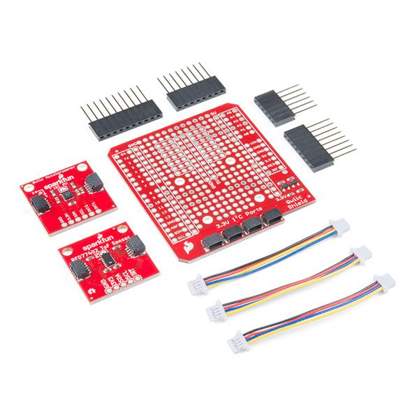
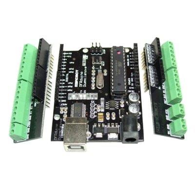
Hardware components

Software apps and online services
Hand tools and fabrication machines
Story
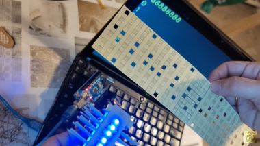
This endeavor is to turn an Arduino UNO into a punchcard-controlled computer whose output results are shown on its serial port (USB to your computer) - as shown here:
https://www.youtube.com/watch?v=yizQKRKVQDU
The six light emitting diodes are hooked up in parallel to be lit up by the Arduino (no special control necessary, they shall just be made to emit light), and opposed each diode shall be one photoresistor. The lights shall be arranged physically in a line, and in a best practicable way shall be so isolated from each other that neighboring lights do not trigger neighboring photoresistors, but each LED only "its own" photoresistor. The photoresistors are to be connected to the A0-A5 analog inputs of the Arduino UNO. The whole setup shall be made so that a carton card can pass between the lights and the photoresistors, and where there are "punches" on the card, the light will shine on the respective LED's resistor - and where the carton is intact, not.
That way, different resistance patterns will be presented to the photoresistors and hence, the Arduino UNO's analog pins, which in turn will allow the Arduino to thus read data from the punchcard. This data is channeled to the internal programming environment, 1V0, in form of numbers, and from there, computation is undertaken whose results are shown through the Arduino UNO's serial port.
Schematics, diagrams and documents
Code
Credits
Related products


Leave your feedback...