
Arduino Display Date And Time On Max7219 8-digit Digital ...

About the project
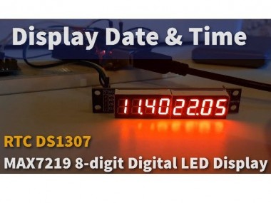
In this tutorial we will learn how to display Date and Time using RTC DS1307 module and MAX7219 8-digit Digital LED Display and Visuino.
Project info
Difficulty: Moderate
Estimated time: 1 hour
License: GNU Lesser General Public License version 3 or later (LGPL3+)
Items used in this project
Hardware components

Story
In this tutorial we will learn how to display Date and Time using RTC DS1307 module and MAX7219 8-digit Digital LED Display and Visuino.
Watch the video.
Step 1: What You Will Need
1 / 5

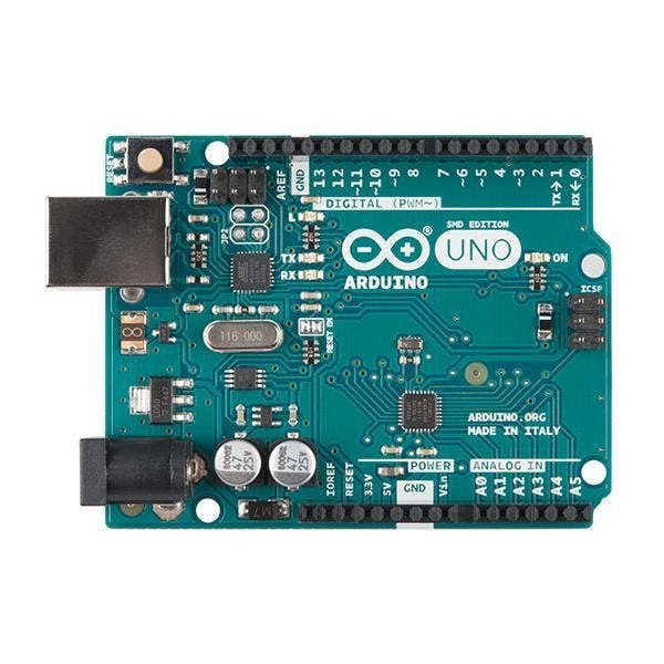
- Arduino UNO (or any other Arduino)
- RTC DS1307 module
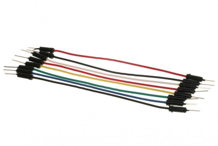
- Jumper wires
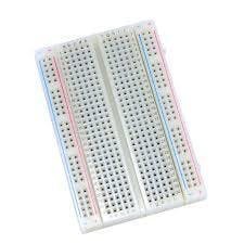
- Breadboard
- Max7219 Led Dot Matrix 8-digit Digital Display Control Module
- Visuino program: Download Visuino
Step 2: The Circuit
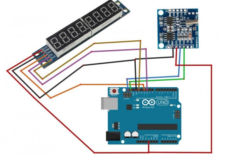
- Connect RTC DS1307 module pin[VCC] to Arduino pin[5V]
- Connect RTC DS1307 module pin[GND] to Arduino pin[GND]
- Connect RTC DS1307 module pin[SDA] to Arduino pin[SDA]
- Connect RTC DS1307 module pin[SCL] to Arduino pin[SCL]
- Connect LED module pin[VCC] to Arduino pin[5V]
- Connect LED module pin[GND] to Arduino pin[GND]
- Connect LED module pin[DIN] to Arduino digital pin[11]
- Connect LED module pin[CS] to Arduino digital pin[10]
- Connect LED module pin[CLK] to Arduino digital pin[13]
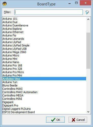
Step 3: Start Visuino, and Select the Arduino UNO Board Type
1 / 2
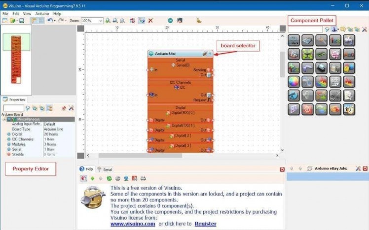
The Visuino: https://www.visuino.eu also needs to be installed. Download Free version or register for a Free Trial.
Start Visuino as shown in the first picture Click on the "Tools" button on the Arduino component (Picture 1) in Visuino When the dialog appears, select "Arduino UNO" as shown on Picture 2
Step 4: In Visuino Add Components
1 / 6
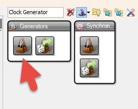
- Add "Clock Generator" component
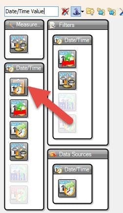
- Add "Date/Time Value" component
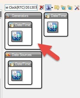
- Add ""Real Time Clock(RTC) DS1307" component
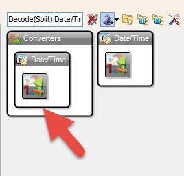
- Add "Decode(Split) Date/Time" component
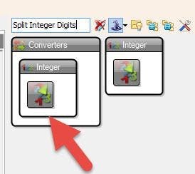
- Add 2X "Split Integer Digits" component
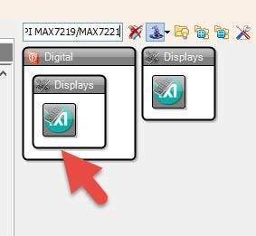
- Add "Maxim LED Display Controller SPI MAX7219/MAX7221" component
Step 5: In Visuino Set Components
1 / 7

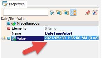
- Select "DateTimeValue1" and in the properties window set Value to your current Date and Time
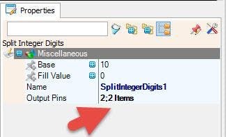
- Select "SplitIntegerDigits1" and in the properties window set Output Pins to 2
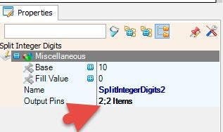
- Select "SplitIntegerDigits2" and in the properties window set Output Pins to 2
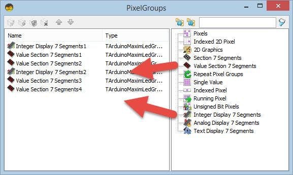
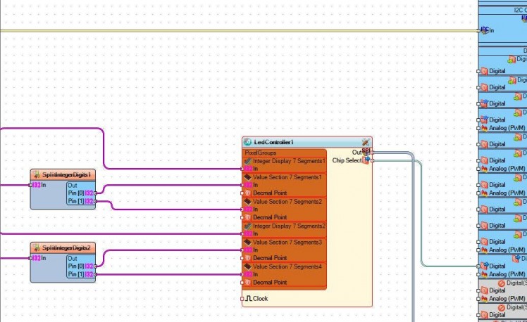
Double click on the "LedController1" and in the "PixelGroups" window drag:
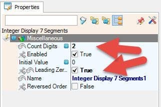
- "Integer Display 7 Segments" to the left side, and in the properties window set "Count Digits" to 2 and "Leading Zeroes" to True
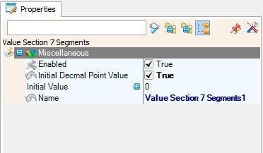
- "Value Section 7 Segments" to the left side, and in the properties window set "Initial Decmal Point Value" to True
- "Value Section 7 Segments" to the left side
- "Integer Display 7 Segments" to the left side, and in the properties window set "Count Digits" to 2 and "Leading Zeroes" to True
- "Value Section 7 Segments" to the left side, and in the properties window set "Initial Decmal Point Value" to True
- "Value Section 7 Segments" to the left side
Close the "PixelGroups" window
Step 6: In Visuino Connect Components
1 / 4
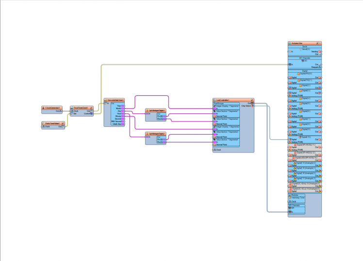
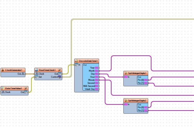
- Connect "ClockGenerator1" pin Out to "RealTimeClock1" pin Clock
- Connect "DateTimeValue1" pin Out to "RealTimeClock1" pin Set
- Connect "RealTimeClock1" pin Out to "DecodeDateTime1" pin In
- Connect "RealTimeClock1" pin Control I2C to "Arduino" pin I2C In
- Connect "DecodeDateTime1" pin Month to LedController1 > Integer Display 7 Segments1 pin In
- Connect "DecodeDateTime1" pin Day to "SplitIntegerDigits1" pin In
- Connect "DecodeDateTime1" pin Hour to "SplitIntegerDigits2" pin In
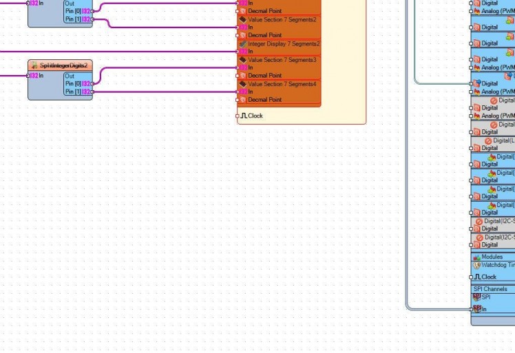
- Connect "SplitIntegerDigits1" pin 0 to LedController1 > Value Section 7 Segments1 pin In
- Connect "SplitIntegerDigits1" pin 1 to LedController1 > Value Section 7 Segments2 pin In
- Connect "SplitIntegerDigits2" pin 0 to LedController1 > Value Section 7 Segments3 pin InConnect "SplitIntegerDigits2" pin 1 to LedController1 > Value Section 7 Segments4 pin In
- Connect "DecodeDateTime1" pin Minute to LedController1 > Integer Display 7 Segments2 pin In
- Connect "LedController1" pin Out SPI to Arduino Pin SPI In
- Connect "LedController1" pin Chip Select to Arduino Digital Pin [10]
Step 7: Generate, Compile, and Upload the Arduino Code
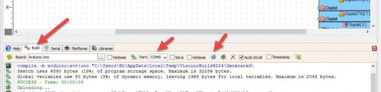
In Visuino, at the bottom click on the "Build" Tab, make sure the correct port is selected, then click on the "Compile/Build and Upload" button.
Step 8: Play
If you power the Arduino module, the LED Display will start to display a Date and Time.
Congratulations! You have completed your project with Visuino. Also attached is the Visuino project, that I created for this tutorial, you can download it and open it in Visuino: https://www.visuino.eu
Schematics, diagrams and documents
Code
Credits
Related products


Leave your feedback...