
8x8 led matrix interfacing with arduino
Made by shahbaz75sb
About the project
I use 788bs, a common anode 8x8 led matrix Modules for this project. Learn how to identify matrix pinout, how to interface with Arduino.
Project info
Difficulty: Moderate
Platforms: Digilent
Estimated time: 1 hour
License: GNU Lesser General Public License version 3 or later (LGPL3+)
Items used in this project
Hardware components

Software apps and online services
Story
There are several types of led matrix displays available in the market. It also comes with Arduino kits. We can understand it in size and types, e.g. 5x7, 8x8, common anode, and common cathode type.
1 / 2 • Led matrix

Led matrix
But in this article, I will discuss 788bs as a common anode 8x8 red color matrix Modules. We use it in many electronics displaying items, e.g. electronics clocks. also for moving message displays, displaying games, etc.
We use a dot matrix display with an Arduino UNO board directly, sometimes in projects. But for some projects, we use a max7219 chip or 74hc595 for dot matrix driver as required in our projects.
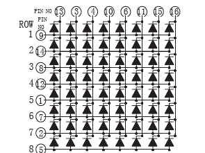
Led matrix Pinout

Led matrix Pinout
8x8 led Matrix Pinout detailsThe dot-matrix modules most of the time comes in red led. It is easy to attach with an Arduino board as compared to an RGB led display.
If we look at a piece of the 8x8 dot matrix, it contains 16 pins in which 8 pins used for rows and 8 for columns. That's mean in rows and column a total of 64 LEDs.We start from Pin # 1 to pin # 8. Pin number 1 is R5 (Row-5) and Pin number 8 is R3(Row-3) at the downside.
At the upper side From Pin 9 (Row-1) to Pin 16 (column-1) located. But a newbie always confuses and starts from zero, because we know the picture/diagram. often we get from some source, also we have to sort out which one +VE and -VE. might be an expert can understand from common cathode/anode type.
But my concern about the person has a basic knowledge of electronics. Who try to make their own initial display projects like a clock or some more.
Ok let’s start if we have an 8x8 dot matrix, And how do we know where pin 1 is? As in IC Chips near Pin 1, a dot mentioned at IC/Microcontroller Chip. But here, how do we know?
Pins Starts at knob side

Pins Starts at knob side
At the led matrix module, the manufacturer writes the tag or mark at pin 1 side, as shown in the figure. We definitely find it. And also a curve mentioned at pin number 1 side.
Battery connection

Battery connection
Row = + Positive Supply
Column = - Negative Supply
The testing power supply should be 1.5V DC required. So the only one battery cell enough or uses one 130 ohm resistance in series at a positive/negative side.
Led matrix Testing with Battery cell

Led matrix Testing with Battery cell
After that attached led to the power supply. We found that the 8th column and 5th rows led become ON as Connection shown in the figure. How to connect the battery cell with a matrix display.
Column and Row Pin connection

Column and Row Pin connection
Pin Test of led dot matrixAs shown in fig pin # 1 and pin # 16 got Energize and 8th Column and 5th-row led become ON. We should verify the Dot-matrix before using it because if any led found blown we can replace it with a good one.
Led matrix light up

Led matrix light up
Programming with Arduino UNOTo run the 788bs, you need to check it with Arduino UNO. What material you need to perform a complete test.
Arduino UNO Amazon
788BS 8x8 matrix Amazon / Banggood
Battery (1.5V) only one
Jumper wires
We often use the dot matrix display with the shift register 74HC595 led driver or max7219. most common in electronic Circuits, we operate it with a Microcontroller or Arduino platform, and even with Raspberry Pi. But in this circuit, you can test the matrix direct with an Arduino UNO board.
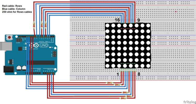
Interface dot matrix with ArduinoFirst setting up the matrix circuit, as per the connection given in the picture diagram. start the Arduino IDE to program the Arduino UNO board. Arduino IDE is available at Arduino official site. For this circuit, it does not need resistance at all. Just connect wires as per the instruction.
Here you need two steps before starting a matrix connection with Arduino as per the 788bs datasheet matrix pins connection given.
1- 8x8 led matrix code generatorThis will help to generate code for your matrix. Just draw anything for the matrix, copy the code, and use it in your program. You can draw different symbols, shapes, or words.
2- Add matrix library with Arduino IdeFirst, add the 8x8 led dot matrix library in Arduino Ide. hereafter, the library manager in Arduino Ide will run the code. It will display in the matrix.
The connection between Led matrix and Arduino UNOMatrix Rows Pins # ------------ Arduino Uno output Pins
Pin # 1 ---------- 2
2 ---------- 3
3 ---------- 4
4 ---------- 5
5 ---------- 6
6 ---------- 7
7 ---------- 8
8 ---------- 9
Matrix Column: Pins # ----------------- Arduino Uno output Pins #
Pin # 1 ------------ 10
2 ------------ 11
3 ------------ 12
4 ------------ 13
5 ------------ A1
6 ------------ A2
7 ------------ A3
8 ------------ A4
Schematics, diagrams and documents
Code
Credits
Leave your feedback...