
3dcg Control Using Touchdesigner & 10 Dof Mems Imu Sensor

Made by DoYouKnowArduino
About the project
I controlled 3DCG object using TouchDesigner. The object moves according to the value of the sensor connected Arduino. By H0meMadeGarbage
Project info
Difficulty: Easy
Estimated time: 3 days
License: GNU General Public License, version 3 or later (GPL3+)
Items used in this project

Story
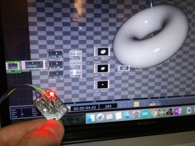
I controlled 3DCG object using TouchDesigner. The object moves according to the value of the sensor connected Arduino.
10 DOF Mems IMU Sensor
https://www.dfrobot.com/product-818.html
This sensor has:
- ADXL 345: 3-axis acceleration sensor
- ITG 3200: 3-axis gyro
- HMC 5883 L: 3-axis geomagnetic sensor
- BMP 085: Barometric pressure sensor
The interface of the module is I2C.
Configuration
Arduino IDE Program
It is based on the library and sample code which can be downloaded below.
https://www.dfrobot.com/wiki/index.php/10_DOF_Sensor_(SKU:SEN0140)Serial output of sensor attitude angle "yaw, pitch, roll". Use the attached code.
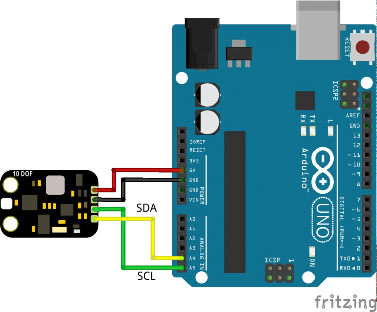
Connection diagram
The following is the total connection diagram.
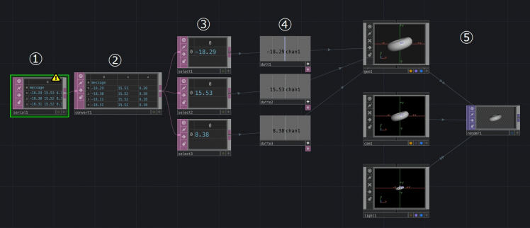
1. Serial data from Arduino acquisition
Select and place the Serial operator from the DAT (Data) tab and obtain serial data from Arduino.
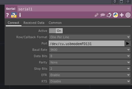
- Port: Select the Arduino port connected to the PC
2. Split serial data
Select and place the Convert operator from the DAT tab and wire it with the Serial operator. Since three data of yaw pitch roll has been sent in one row, Tab divides the data into three columns.
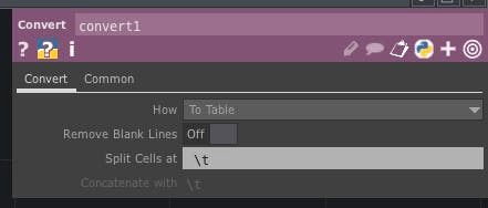
- Data division with Tab ( t)
3. Selection of serial data.
Select and place the Select operator from the DAT tab and connect with the Convert operator so that only the latest serial data is acquired. Place three and get the latest data of yaw pitch roll respectively.
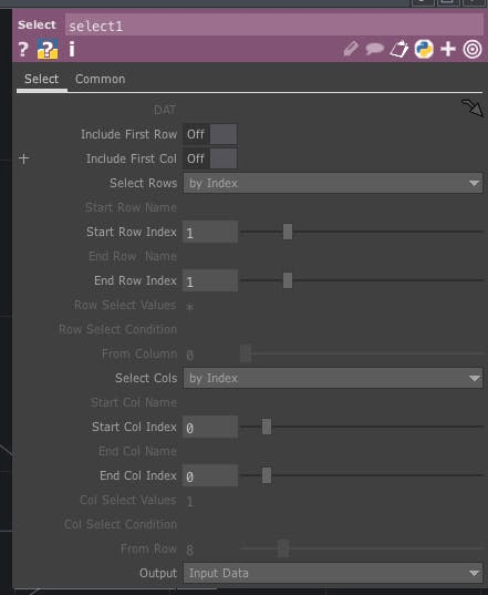
- Select Rows: By Index
- Start Row Index, End Row Index: 1
- Select Cols: by Index
- Start Col Index, End Col Index: Select 0, 1, 2 respectively to get yaw pitch roll
4. Convert latest serial data to CHOP data
Select and place the DAT to operator from the CHOP tab and convert the serial data of the DAT value to the value for CHOP. Place three for yaw pitch roll.
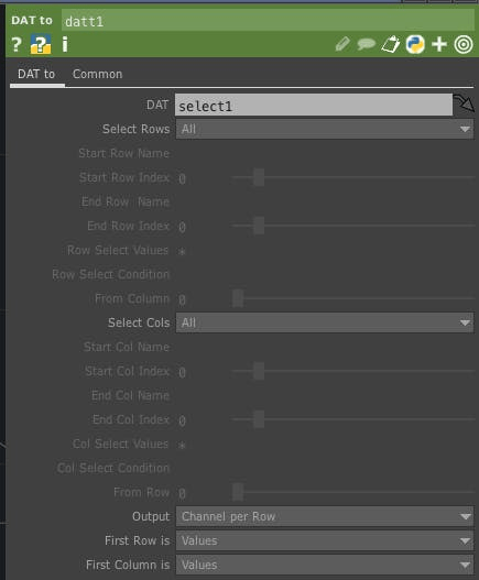
- Drag each Select operator to DAT
- First Column is: Values
5. Place 3DCG and enter yaw pitch roll data
Select and place the Geometry, Camera, Light Operator from the COMP tab and the Render operator from the TOP tab. When placed, they are wired automatically and CG is displayed by clicking the blue circle on the lower right of the Render operator. Connect Geometry operator and yaw pitch roll data and move CG.

Geometry Operator Properties
- Rotate: Drag the DAT to operator to roll to x, yaw to yaw, and z to pitch respectively (Before dragging, it is necessary to click "+" in the lower right of DAT to operator and put it in View mode)
- Scale: Set x, y, z to 0.5
Operation
Code
Credits
DoYouKnowArduino
Offering quality microcontroller, shield, sensors, electronic components, iot gateway/node and robot kit with arduino, lattepanda, raspberry pi and intel edison/cuire/joule.
Related products


Leave your feedback...