
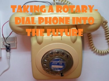
Taking a Rotary-Dial Phone Into the Future
Made by talofer99
About the project
A blast from the past - or a call from the past?
Project info
Difficulty: Moderate
Estimated time: 1 hour
License: GNU Lesser General Public License version 3 or later (LGPL3+)
Items used in this project
Hardware components

Story
When I grew up we only had rotary dial phones for many years, I love them, love the sound they make and been wanting to take one and make it into a mobile phone for many years.
So I was super happy when a good friend (thanks Ilanit) told me she got one for me. The first task was to take it apart and figure out how the dial works.
I cover the subject in the following video.
The code that I'm using for the test is this one:
// include the library code:
#include <LiquidCrystal.h>
// initialize the library with the numbers of the interface pins
LiquidCrystal lcd(12, 11, 10, 9, 8, 7);
#define INDIALPIN 3
#define PULSEPIN 2
boolean inDialPinLastState;
boolean pulsPinLastState;
byte counter = 0;
void setup() {
 Serial.begin(115200);
 Serial.println("System started");
 // set up the LCD's number of columns and rows:
 lcd.begin(16, 2);
 // set the fixed text
 lcd.setCursor(0, 0);
 pinMode(INDIALPIN, INPUT_PULLUP);
 pinMode(PULSEPIN, INPUT_PULLUP);
 inDialPinLastState = digitalRead(INDIALPIN);
 pulsPinLastState = digitalRead(PULSEPIN);
}
void loop() {
 boolean inDialPinState = digitalRead(INDIALPIN);
 boolean pulsPinState = digitalRead(PULSEPIN);
 if (inDialPinState != inDialPinLastState) {
   if (!inDialPinState) {
     Serial.println("Start of dial");
     counter = 0;
   } else {
     Serial.println("End of dial");
     Serial.print("Dialed Digit - ");
     Serial.println(counter);
     if (counter) {
       if (counter == 10)
         counter = 0;
       lcd.print(counter);
     }
   } //end if
   inDialPinLastState = inDialPinState;
 } //end if
 if (pulsPinLastState != pulsPinState) {
   if (!pulsPinLastState) {
     counter++;
   } // end if
   Serial.println("pulsPinState - " + String(pulsPinState));
   pulsPinLastState = pulsPinState;
 }
}
At this stage I was still working on a mega2560 and the main reason was that I already had a full working code from the "call for Tic-Tac-Toe" project that you can watch here.
But since I knew I want to have internet access as well I moved to an ESP32.
Also I wanted to use a SIM800, since they have a really small modules. I had to add a logic level converter and a step down for the SIM800.
In this video, I cover the move and how it was done:
I really wanted to get an UI of some kind and was not very happy with the idea of adding a screen, mainly since it meant cutting the phone box some how.
Then I remembered the cool text to speech library that I have used in the past. and went on testing it on the system. and with out a doubt I found the right UI.
I cover it in this video:
The code that I'm using for the speech test is this:
#include <Arduino.h>
#include <ESP8266SAM.h>
#include <AudioOutputI2S.h>
AudioOutputI2S *out = NULL;
void setup()
{
 out = new AudioOutputI2S();
 out->begin();
}
void loop()
{
 ESP8266SAM *sam = new ESP8266SAM;
 sam->Say(out, "welcome back!");
 delay(500);
 sam->Say(out, "I am an E S P thirty two.");
 delay(50);
 sam->Say(out, "that can talk!");
 delete sam;
 while(1);
}
This is the link for the SAM library.
https://github.com/earlephilhower/ESP8266SAM
The next big thing I had to handle was the ringer.
I really wanted to get the original ringer to work, and I did, but it meant using at least one H bridge, bot the power to at least 12V and add some other parts.
I then (thanks to Ofer) turned to use the speaker I was using for the UI.
found a simple code that play an mp3 and downloaded a recording of a rotary phone ringing.
I also got all the parts soldered on one PCB.
I cover all this exciting stage in this video:
Once I had it all soldered and working I turned to take care of the wiring inside.
I rewired some of the parts with the wires (mainly for the ending) from the original loom.
I added new loom from the esp board to both the dial, button and sound.
Soldered ending to all the wires and reused the phone old connection strips on the back.
After making sure it all worked, I also added in the code the ESP WiFi tool that Ofer and I worked on for few months, this is mainly so I can have an AP portal on it for OTA, which is highly needed when the phone is with the cover.
All you need to do to activate it is to dial 9 (the digit) when the phone is on the hook.
I cover all of this in this video:
Links to our WiFi tool and info on it in this video:
The phone now is almost complete, I only have to change the power cable.
I plan to take the original cable and adjust the end to be an USB one.
Hope you enjoyed it as much as I did.
I will post updates.
** update - I finished the usb cable with replacing the original cable socket.
Schematics, diagrams and documents
Code
Credits
Related products


Leave your feedback...