

Smartsense - A Smart Assistive System For Blind People

Made by dhairya-parikh / Voice
About the project
A system for the blind which helps them walk through the street, as and also monitors their location and sends an SOS on button press.
Items used in this project
Hardware components

Software apps and online services
Story
The story
Blind people face a lot of problems when it comes to commuting from one place to another. All they have for their support is a normal stick, which extends upto just some centimeters, making them prone to falls and hence injuries. Another problem is these people are not accepted by the current society. So, no one comes to help them when they are in some danger or problem.
So, what's the solution to this problem?
Its SmartSense!
The Solution
So, to tackle the above problem I have created a system just for them. This system is equipped with obstacle detection in close proximity using an ultrasonic sensor, GPS integration for Location services and Audio output for the Blind person, accessible via a 3.5 mm audio jack.
Moreover, there will be an android app for the people willing to help such people. So, whenever the SOS switch is turned on, the user will get an alert in his app.
But which device packs all these features into a single board? Its the Sony Spresense!
Here is some main features of this board along with its extension board, as stated on the Developer's Website:
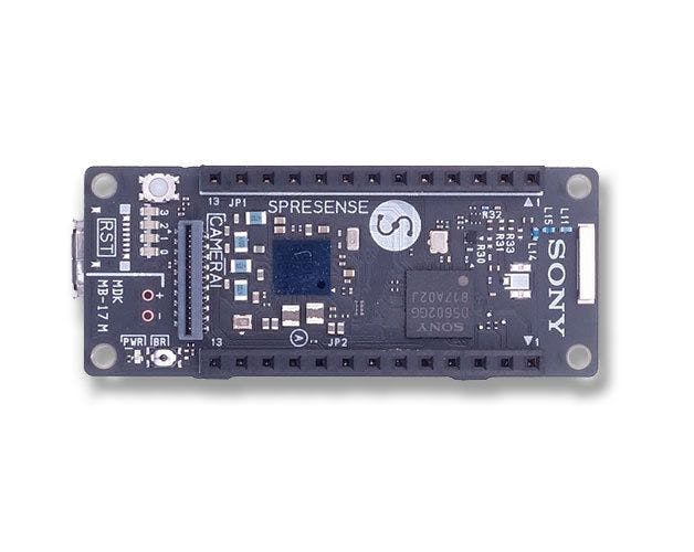 The Spresense
Spresense - made for IoT development
Spresense is a compact development board based on Sony’s power-efficient multicore microcontroller CXD5602. It allows developers to create IoT applications in a very short time and is supported by the Arduino IDE as well as the more advanced NuttX based SDK.
- Integrated GPS - The embedded GNSS with support for GPS, QZSS and GLONASS enables applications where tracking is required.
- Hi-res audio output and multi mic inputs - Advanced 192kHz/24 bit audio codec and amplifier for audio output, and support for up to 8 mic input channels.
- Multicore microcontroller - Spresense is powered by Sony's CXD5602 microcontroller (ARM® Cortex®-M4F × 6 cores), with a clock speed of 156 MHz.
For more details on the Sony Spresense Main, Extension and Camera Boards, please head to the links give below:
Now, lets start with the project.
Starting with the Hardware Part
So, the Hardware includes of the following components:
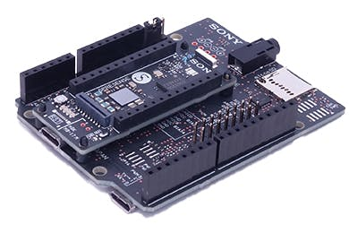
- Sony Spresense Main and Extension Board
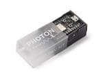
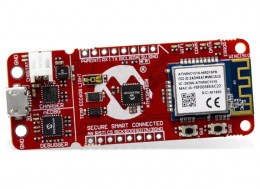
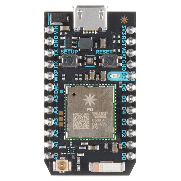
- Particle Photon
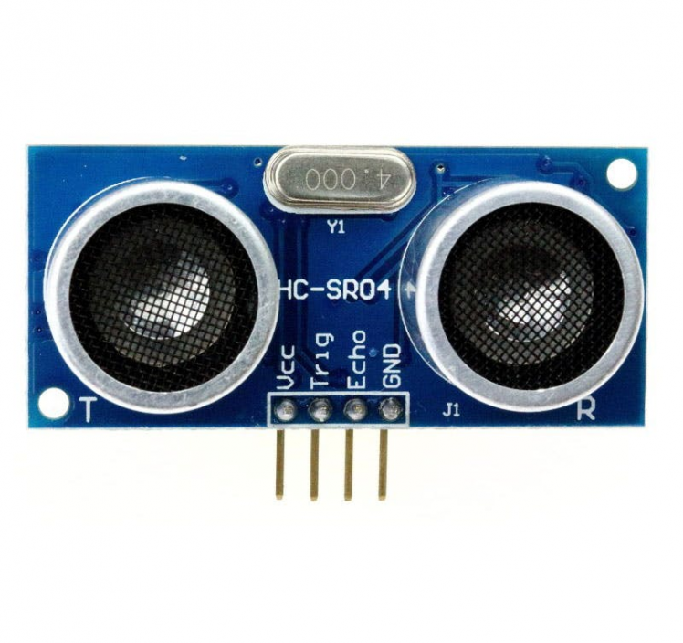
- Ultrasonic Sensor
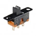
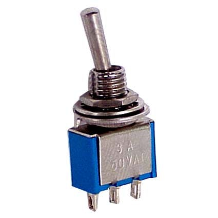
- Button or Switch ( I used a 3 pin toggle Switch)
Finally Getting Started
This are the main parts required for the project. Now to start with this project, we first need to setup our Arduino IDE so that we can program our Spresense board through it.
To do that, just follow the link below for a step by step guide to do so, provided on the Developer's website of Sony:
Now, after this is is done, you are ready to code.
Coding for the Spresense Board
Now that you have your Arduino IDE set, we can first have a look at the provided examples to test the new features the board has. To load the examples, just go to:
File >> Examples >> Examples for Spresense
Now, test the all the examples and analyse their code to understand its functionality. For this project, I would suggest you to go through the following examples:
- SDHCI >> read_write
- Audio>>application >> player
- GNSS >> gnss.ino
Note : To run this example, you need to first run the mp3_dec_installer in the dsp_installer option of Audio examples, as the player example plays a mp3 file placed in your SD Card.
Now, before writing the final code, lets have a look at the ultrasonic sensor code for the Arduino.
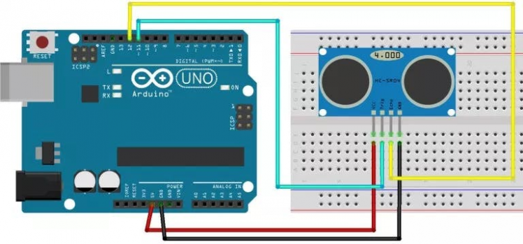
Code for the same:
int trigPin = 11;    // Trigger
int echoPin = 12;    // Echo
long duration, cm, inches;
void setup()
{
     //Serial Port begin
     Serial.begin (9600);
     //Define inputs and outputs
     pinMode(trigPin, OUTPUT);
     pinMode(echoPin, INPUT);
}
void loop()
{
    // The sensor is triggered by a HIGH pulse of 10 or more microseconds.
    // Give a short LOW pulse beforehand to ensure a clean HIGH pulse:
    digitalWrite(trigPin, LOW);
    delayMicroseconds(5);
    digitalWrite(trigPin, HIGH);
    delayMicroseconds(10);
    digitalWrite(trigPin, LOW);
    // Read the signal from the sensor: a HIGH pulse whose
    // duration is the time (in microseconds) from the sending
    // of the ping to the reception of its echo off of an object.
    pinMode(echoPin, INPUT);
    duration = pulseIn(echoPin, HIGH);
    // Convert the time into a distance
    cm = (duration/2) / 29.1;
    // Divide by 29.1 or multiply by 0.0343
    Serial.print(cm);  Serial.print("cm");
    Serial.println();
    delay(250);
}
This simple code gets the Ultrasonic Data in centimeters and prints it on Serial Monitor.
Ultrasonic + Audio Integration
Now that we have all the knowledge we need, we will write a code which will do the following task:
The system measures the Distance using the Ultrasonic Sensor, and analyses the output to give an audio output of one of the following strings:
No Obstacles Detected (no nearby obstructions)Caution! Near By Obstacles are detected (in close proximity)Danger! Mind Your Step! (Obstruction very close to you)
To do this, we will use the method used in the above stated examples. Follow this steps now:
1. Create 3 audio mp3 files with the sentences shown in the above task. After that, store them in the root storage of your SD Card (assuming you have the mp3_dec in the BIN Folder), so that you can access them via code.
2. After that, start with the code. Here are the include statements to :
#include <SDHCI.h>     //SD Card Access Library
#include <Audio.h>     //Audio Library
After that, create objects for sdcard and audio to access its functions during our program.
SDClass theSD;    //SD Card Class Object
AudioClass *theAudio;    //Audio Class Object

File myFile;  //For File open(mp3 files in our case)
Next comes the variable declarations:
int trigPin = 11;    // Trigger
int echoPin = 12;    // Echo
long duration, cm;
String result;
bool ErrEnd = false;
Now, simply copy the void setup() of the player.ino example, and make some changes:
void setup()
{
 //Serial Port begin
 Serial.begin (115200);
 sleep(1);
 //Define inputs and outputs
 pinMode(trigPin, OUTPUT);
 pinMode(echoPin, INPUT);
 // start audio system
 theAudio = AudioClass::getInstance();
 theAudio->begin(audio_attention_cb);
 puts("initialization Audio Library");
 /* Set clock mode to normal */
 theAudio->setRenderingClockMode(AS_CLKMODE_NORMAL);
 theAudio->setPlayerMode(AS_SETPLAYER_OUTPUTDEVICE_SPHP, AS_SP_DRV_MODE_LINEOUT);
 err_t err = theAudio->initPlayer(AudioClass::Player0, AS_CODECTYPE_MP3, "/mnt/sd0/BI   N", AS_SAMPLINGRATE_AUTO, AS_CHANNEL_STEREO);    // This comes in a single line
 /* Verify player initialize */
 if (err != AUDIOLIB_ECODE_OK)
   {
     printf("Player0 initialize errorn");
     exit(1);
   }
}
Next comes the void loop(), which will be as follows:
void loop()
{
 err_t err = theAudio->initPlayer(AudioClass::Player0, AS_CODECTYPE_MP3, "/mnt/sd0/BIN", AS_SAMPLINGRATE_AUTO, AS_CHANNEL_STEREO);   //comes in a Single Line
 digitalWrite(trigPin, LOW);
 delayMicroseconds(5);
 digitalWrite(trigPin, HIGH);
 delayMicroseconds(10);
 digitalWrite(trigPin, LOW);
 pinMode(echoPin, INPUT);
 duration = pulseIn(echoPin, HIGH);
 // Convert the time into a distance
 cm = (duration/2) / 29.1;     // Divide by 29.1 or multiply by 0.0343
 if(cm >=60)
 {
   result = "No Obstacles or pits detected";
   Serial.println(result);
   myFile = theSD.open("Voice2.mp3");
   err = theAudio->writeFrames(AudioClass::Player0, myFile);
   theAudio->setVolume(-160);
   theAudio->startPlayer(AudioClass::Player0);
   theAudio->stopPlayer(AudioClass::Player0);
   myFile.close();
 }
 else if((cm>=30)&&(cm<=60))
 {
   result = "Caution! Nearby Obstacles Detected";
   Serial.println(result);
   myFile = theSD.open("Voice3.mp3");
   err = theAudio->writeFrames(AudioClass::Player0, myFile);
   theAudio->setVolume(-160);
   theAudio->startPlayer(AudioClass::Player0);
   theAudio->stopPlayer(AudioClass::Player0);
   myFile.close();
 }
 else
 {
   result = "Danger! Mind your step";
   Serial.println(result);
   myFile = theSD.open("Voice4.mp3");
   err = theAudio->writeFrames(AudioClass::Player0, myFile);
   theAudio->setVolume(-160);
   theAudio->startPlayer(AudioClass::Player0);
   theAudio->stopPlayer(AudioClass::Player0);
   myFile.close();
 }
 delay(4000);
}
So, this wraps up the code. Here is the video tutorial of the following code:
Now, that this functionality is done, lets move to the GPS part of the project.
GPS Integration with the Project
One of the most exciting features of the Sony Spresense board is the on-chip GPS, which makes it a far more superior board then its competitors. The best part is that its coding part is very easy, thanks to Sony for creating a dedicated library for the same.
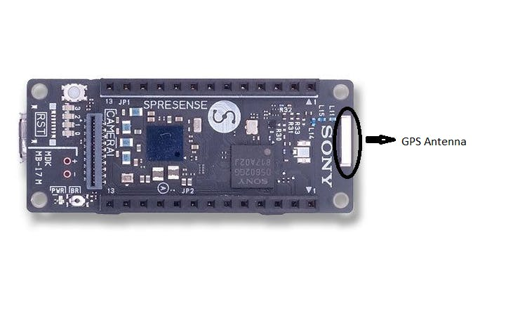 That tiny thing is a GPS Antenna!!
So, to study this, we will use the gnss.ino example as it is as it provides all the information we need.
The code is attached below. Please note that it takes upto 10 minutes to get a position fix on the GPS initially, as when you start it for the first time, it is a COLD_START for the GPS. Learn more about this by following the link below:
Now, after you know enough about it, lets see how the output of the example code looks like on the Serial Monitor:
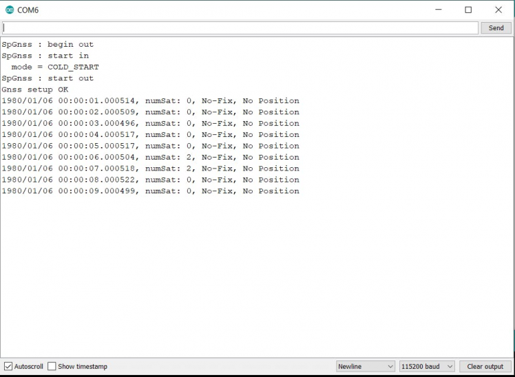 Serial Monitor for gnss.ino sketch
Send Data to Photon
Now, in my final code I have clubbed both these features into a single code. The code is attached below. Please comment if you have any doubt. Now, to the next step, that is to send this data to the Particle Photon.
There are quite some options for this data exchange, which are listed below:
- Serial Transfer(UART)
- I2C Tranfer
- SPI
For simplicity, I have used the most simple UART method for serial data transfer. To do this, I referred this Awesome Tutorial by rickkas7.
Do the following connections between the Spresense and the photon:
- Photon TX connects to Arduino RX (0)
- Photon RX connects to Arduino RX (1)
- Photon GND connects to Arduino GND
Now here are the codes for Arduino and Photon respectively.
Arduino Code:
// Constants
const size_t READ_BUF_SIZE = 64;
// Forward declarations
void processBuffer();
// Global variables
char readBuf[READ_BUF_SIZE];
size_t readBufOffset = 0;
void setup()
{
 // Serial TX (1) is connected to Photon RX
 // Serial RX (0) is connected to Photon TX
 // Ardiuno GND is connected to Photon GND
 Serial.begin(9600);
}
void loop()
{
 // Read data from serial
 while(Serial.available()) {
   if (readBufOffset < READ_BUF_SIZE) {
     char c = Serial.read();
     if (c != 'n') {
       // Add character to buffer
       readBuf[readBufOffset++] = c;
     }
     else {
       // End of line character found, process line
       readBuf[readBufOffset] = 0;
       processBuffer();
       readBufOffset = 0;
     }
   }
   else {
     readBufOffset = 0;
   }
 }
}
void processBuffer()
{
 int receivedValue = atoi(readBuf);
 // This program just increments the value sent by the Photon and returns it
 Serial.print(receivedValue + 1, DEC);
 Serial.print('n');
}
Particle Photon Code:
#include "Particle.h"
// Constants
const unsigned long SEND_INTERVAL_MS = 2000;
const size_t READ_BUF_SIZE = 64;
// Forward declarations
void processBuffer();
// Global variables
int counter = 0;
unsigned long lastSend = 0;
char readBuf[READ_BUF_SIZE];
size_t readBufOffset = 0;
void setup()
{
	Serial.begin(9600);
	// Serial1 RX is connected to Arduino TX (1)
	// Serial2 TX is connected to Arduino RX (0)
	// Photon GND is connected to Arduino GND
	Serial1.begin(9600);
}
void loop()
{
	if (millis() - lastSend >= SEND_INTERVAL_MS) {
		lastSend = millis();
		Serial1.printlnf("%d", ++counter);
		Serial.printlnf("Sent to Arduiuno: %d", counter);
	}
	// Read data from serial
	while(Serial1.available())
	{
		if (readBufOffset < READ_BUF_SIZE)
		{
			char c = Serial1.read();
			if (c != 'n')
			{
				// Add character to buffer
				readBuf[readBufOffset++] = c;
			}
			else
			{
				// End of line character found, process line
				readBuf[readBufOffset] = 0;
				processBuffer();
				readBufOffset = 0;
			}
		}
		else
		{
			Serial.println("readBuf overflow, emptying buffer");
			readBufOffset = 0;
		}
	}
}
void processBuffer()
{
	Serial.printlnf("Received from Arduino: %s", readBuf);
}
When you flash both these codes, you will get the following output:
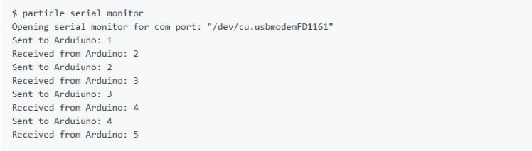 Sample Output
Now, simply implement this concept in your final code. In my code, I opened the serial(115200) for my connection and serial1 port for USB serial connection.
So, now we are done with the coding part.
Sending this received Data to Firebase Database (Skip if you are going to follow my project)
Now that we have the data we need, we will be pushing this data to a Firebase Real time Database, so that we can access it later or for our Android App. Due to time constraint, I will be using a Blynk App for this project. But, here I am showing how to setup the firebase and integrate it with Photon.
So, to do that, we have to simply publish our obtained results to the Particle Console and create a Webhook of something like this:
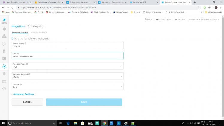 1 / 2 • Webhook for Particle
So, now we will be creating a similar Webhook to connect our Firebase Database to our Particle Photon.
FireBase Initialization
We need to first create a new firebase project. To do so, you need a google account, using which you sign in to through following URL:
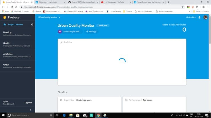
You will see the sign in option as shown in the figure below, from which you sign into your google account and then go to the Console using the Go to Console option shown in the image below.

The Console looks something like this:
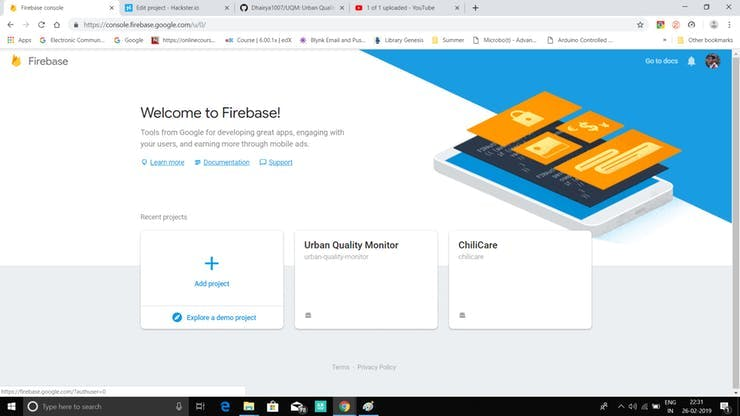 Firebase Console
Create a new project now:
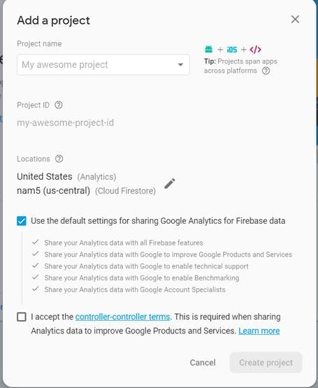 New Project creation.
Once done, you will be redirected to project homepage.
Now, go to Develop > Database and create a real-time Database.
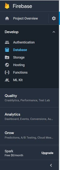 1 / 2
1 / 2
Add the fields and shown in the above picture for this project, or you can add your own fields too if you have some knowledge or have previously worked with firebase.
Now, to link an Android application to the Firebase Database, just follow this easy tutorial shown in the video below:
Complete tutorial video by E AngkorThis completes our Fire Base Setup and its Integration with the Photon. Now you can easily integrate this Database to your android app by following the video tutorial below :
Tutorial by PARBEESH R KHowever, for this project, due to a shortage of time, I will be creating a Blynk App. Due to Indian customs, I just received the boards a few days back. You can even see my project - UQM for android firebase Interface along with the source code.
Blynk App Setup
The steps to create a new project in Blynk are:
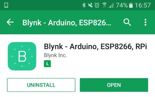
1. Download the Blynk app from the play store.
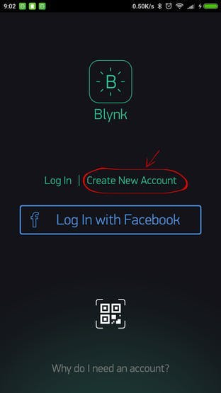
2. Sign up to create a free account and start developing apps.
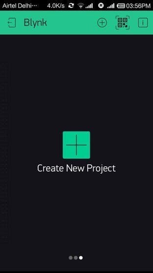
3. After that, create a new project and the choose the particle photon under boards section and the WiFi option and hit create.
4. Now your project is created and you are ready to app the required components to your Android App. My final app looks something like this:
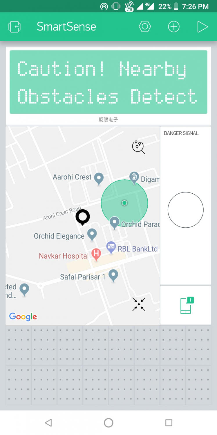 1 / 2 • App View
The Black marker shown in the Map is generated by the location data sent through the Particle Photon. The Danger signal marked widget is an LED, which turns on when the SOS switch on the device is pressed. The app notifications looks like:
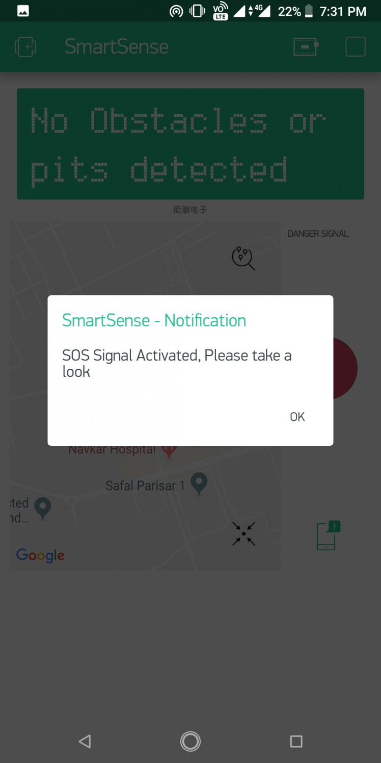 1 / 3 • In App Notification
This is how the whole system operates. You have live location on the app, SOS Notification and also for some additional information, I also added the Ultrasonic results to the app too.
Note: Please keep in mind that the actual Hardware has an Audio out in the form of a 3.5 mm Audio Out, so the Blind Person will have voice data access continuously, that app is just for monitoring purpose.
The Final System
So, after combining all the above parts and assembling all the parts together, I got all of this into a custom made Cardboard box( made by me :) ), these are the final images of my system.
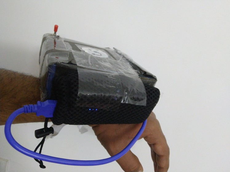 1 / 5 • The Final System, on my Awesome Hand!!
So, this was all for the Hardware and the Software Part of the project.
Now comes the fun part, the Video Showcase!
Video Showcase of SmartSenseThis marks the end of this Project. For all the code, just follow on to the GitHub repository linked below.
About the Sony Spresense Camera
As you have seen, I also have mentioned the Sony spresense camera in the required things, but due to shortage of time, I couldn't get any time to look into the camera specifics, I could just take and carry on basic analysis on the image, like ISO settings, White Balance, etc.
 The Beast! Camera Board
I would really like to apologize the contest organizers, who sent me the camera board, but due to time shortage, I couldn't include that feature on my project. But I will surely be posting a project related with Machine Learning on Spresense, so please guys! stay tuned.
To know more about the camera, just follow the below link to an awesome Hackster project for one of the Hacksterers : jpenner64
Vote of Thanks
I would like to thank Sony and Hackster for organizing such a great contest, where in we could get the most out of the Sony Spresense series of Boards.
Thank you for giving me a chance to showcase my skills and sending me the Hardware, which made this project possible.
Leave your feedback...