
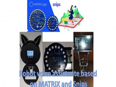
Robot Voice Assistante Based On Matrix And Snips
Made by electrouser865
About the project
This project incorporates the Snips voice assistant, the Matrx Voice development system and two robot assistants.
Project info
Items used in this project
Hardware components


View all
Story
In recent years there has been a growing interest in voice assistants. Large companies such as Amazon, Google, Microsoft and Apple, have introduced their devices. These allow us to control objects in our home (lights, TV, etc.), using voice commands. At the same time, these devices allow us to access news, listen to music, access our calendar of appointments, etc.. However, one of the problems these applications have is the ability to develop new applications. With Alexa it is possible to quickly make applications or skills, however, when you want to connect these applications with our developments is very complicated. The advantage of this device is that being open source is much easier to connect to our projects and thus increase our applications. Auxiliary robots represent one of the best elements to accompany elderly people and it is very important that these robots have image and voice recognition systems.
However, we have always thought that the system that recognises the human voice must be embedded inside the robot and form an integral part of it. The proposal presented in this project tries to break with this paradigm and create one in which the voice recognition system is decoupled from the robot (Figure 1). Thus allowing a versatility when interacting with the robot or with other elements that are in our home.
Figure 1, general structure of the system.

Figure 1, general structure of the system.
For this reason I have divided my project into 4 small sub-projects, where each of them has a complete communication are the assistant. These small projects are listed below:
1. Voice Assistant using Matrix Voice
2. Mobile Assistant Robot
3. DeskRobot Assistant
Voice Assistant using Matrix Voice
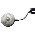
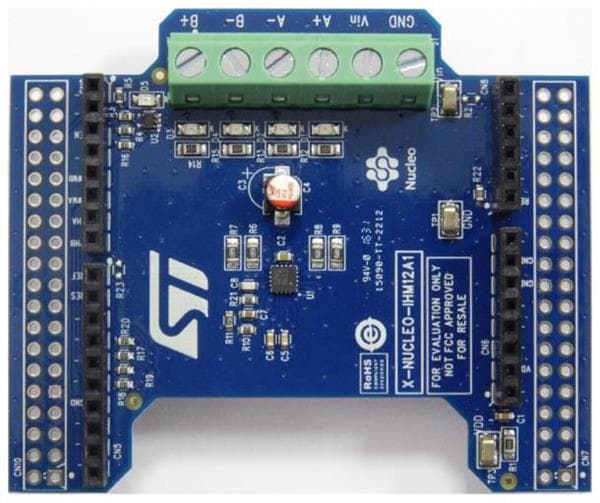
The system presented below uses a series of software and hardware tools, which are interconnected with each other. The first tool is the voice capture system, which is made up of the Matrix Voice development card (Figure 2).

Figure 2, Matrix Voice Development Card
This development board has the following features:
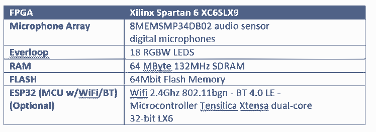
Matrix Voice connects to a Rapberry Pi 3B+, through its input and output ports. Once connected to the raspberry, the next step is to install the software that allows processing the acquired sounds. The first step is to install the necessary libraries to control the Matrix Voice, MATRIXIO Kernel Modules is the kernel driver for MATRIX Creator and MATRIX Voice, the following instructions allow you to install this kernel.
sudo apt-get install --reinstall raspberrypi-bootloader raspberrypi-kernel# Add repo and keycurl https://apt.matrix.one/doc/apt-key.gpg | sudo apt-key add -echo "deb https://apt.matrix.one/raspbian $(lsb_release -sc) main" | sudo tee /etc/apt/sources.list.d/matrixlabs.list# Update packages and installsudo apt-get updatesudo apt-get upgrade# Reboot in case of Kernel Updatessudo reboot# Installation MATRIX Packagessudo apt install matrixio-kernel-modules# Rebootsudo rebootThe next step is to modify the file /etc/asound.conf, this file must have the following format (https://community.matrix.one/t/cant-get-snips-and-matrix-to-work-after-following-tutorial/2632/12):
pcm.!default {type asymcapture.pcm "mic"playback.pcm "speaker"}pcm.mic {type softvolslave {pcm "array"}control {name "MicArray Master"card "MATRIXIOSOUND"}}pcm.speaker {type plugslave {pcm "hw:0,0"rate 16000}}pcm.array {type plugslave {pcm "hw:MATRIXIOSOUND"}}Once the MATRIX Voice drivers are installed, the next step is to install Snips.
sudo npm install -g snips-sam
At the end of the Snips installation, it is necessary to modify the "snips.toml", which is located in /etc/snips.toml. The modifications to be made are as follows
[snips-audio-server]Mike = “MATRIXIO-SOUND: - (hw:2,0)”portaudio_playback = "default"Up to this point we have configured our Snips to be used with the MATRIX Voice, the next thing is to configure our Snips and we follow the next steps:
1. sam connect <IP Raspberry Pi>
a. Username: pi
b. Password: “your password”
2. sam init
3. sam test speaker
4. sam test microphone
Now the next step is to create our wizard, for this we go to the Snips website: https://console.snips.ai/login
If we don't have an account, we create one and if you already have one, you access it. The wizard created for this project consists of four intentions and slots (Figure 3):

Figure 3, Assistant Intentions and Slots
Since we already have our wizard built into our Snips console, the next thing to do is to install the wizard inside our raspberry. To do this we use the following command:
sam install assistantIn the console it shows us a list of the assistants that we have registered in our account of Snips, we select the assistant that in my case is Snips-Robot. The installation of the source code of the wizard (which for my case was done in Pyton), is in the following path:
/etc/lib/snips/skils/"assistant_name".Having installed our wizard and as we know that the Sam system is a command line interface (CLI) tool. It was created to easily configure and maintain Raspberry Pi and similar devices directly from your computer, without having to create an SSH session and type complex, low-level commands. The list of commands accepted by Sam can be found at the following link: https://docs.snips.ai/reference/sam
The Snips platform messages are transmitted as MQTT messages, which is why it is necessary to subscribe to our services in our source code. This subscription will allow us to send and receive the messages of each of the elements that make up the wizard. The services that are registered inside the assistant, are the following ones:
hermes/dialogueManager/startSessionhermes/intent/jarain78:controlling_snips_robothermes/intent/jarain78:snips_robot_interactionhermes/intent/jarain78:snips_robot_meteo
Figure 4, Case of Voice Assistant

Figure 5, Voice Assistant
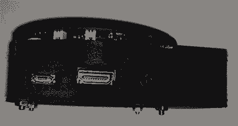
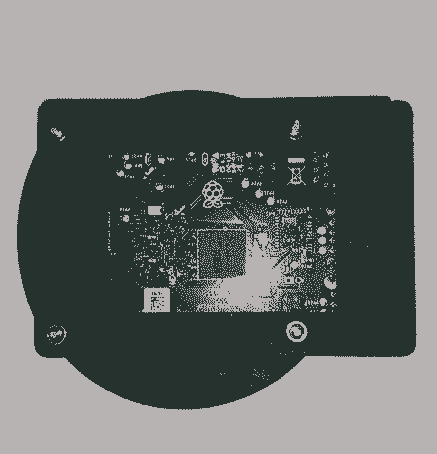

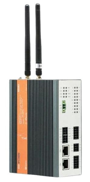
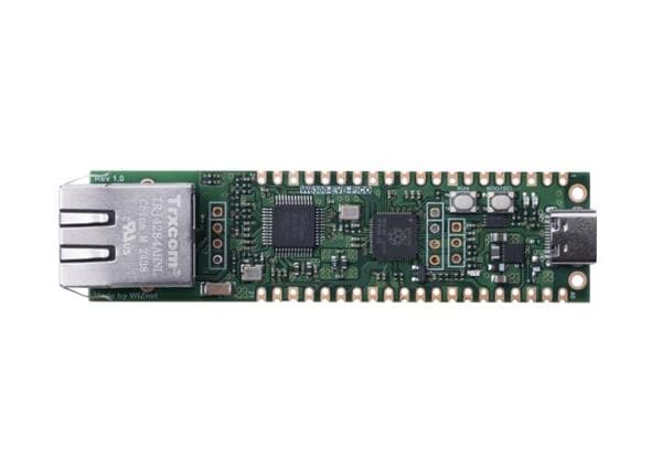
Figure 6, Voice Assistant and Rapid IoT device
Mobile Assistant Robot
Up to this point we already have the first part of our system, the next step is the construction of the robot. To make this construction I used an aluminum structure (Figure 7):
Figure 7, SWMAKER All Black/Silver Hypercube 3DPrinte

Figure 7, SWMAKER All Black/Silver Hypercube 3DPrinte
Figure 8 shows a 3D design made using the SolidWorks tool, this is one of the many shapes the robot could have. Because, when working with modular systems, the robot could have any shape.

Figure 8, 3D Robot Model
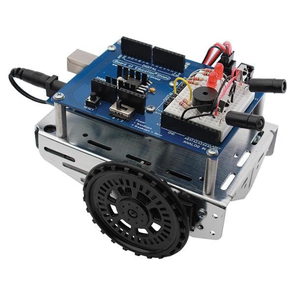
The following Figure 9[A-E] shows the assistant robot that we want to control through our assistant.
Figure 9A

Figure 9A
Figure 9B

Figure 9B
Figure 9C

Figure 9C
Figure 9D

Figure 9D
Figura 9E, Robot

Figura 9E, Robot
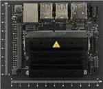
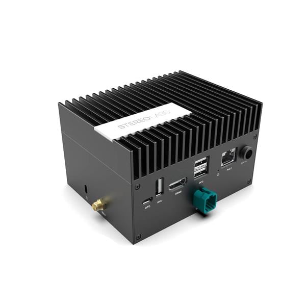
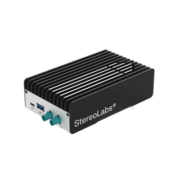
The robot is divided into two sections that help control the robot, the first is in charge of an Arduino Mega 2560 and the second uses a Jetson Nano (Figure 10). The Arduino is in charge of controlling everything related to the low level of the robot, i.e. it controls motors and some Sharp GP2Y0A2YK0F distance sensors. These sensors are used to give the robot a reactive control in case of detecting objects at a certain distance. On the other hand, the Jetson Nano that in this case only does the task of receiving the commands from the assistant (located in the raspberry), these commands as: Forward, Back, Left and Right.

Figure 10, Jetson Nano
They are translated and sent to the Arduino using an RS-232 communication protocol. The message sent to the Arduino is serialized in JSON format, which is deserialized by the Arduino extracting the different elements. The message sent to the Arduino is as follows:
"Stop_robot": "False", "direction": "True", "linear_speed": "0.2", "angular_speed": "0.0"}This message is composed by 4 fields, two boolean and two float, the boolean fields allow the direction control of the motors (CW or CCW) and the stop of the motors. The other two fields are linear speed and angular speed. For safety reasons the maximum speeds have been limited to 0.2, which in PWM translates to 20% of the total speed.
The motors used by the robot are two hooverboard motors (Figure 11).
Figura 11, Hooverboard

Figura 11, Hooverboard
The configuration of the hall encoder connections and the motor power cables are shown in Figure 12.
Figure 12. Motor Connections.

Figure 12. Motor Connections.
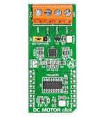
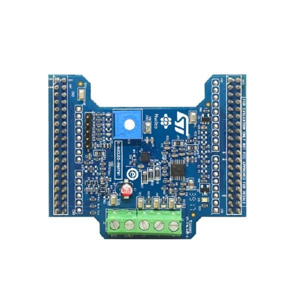
To control these motors, it is necessary to have an ESC control for each motor. This controller has to support a voltage of 36V, for this reason we have used an ESC with MODET transistors this controller is shown below (Figure 13).

Figure 13, Engine ESC Controller
Figurea 14 shows the different connections made to control the motors (The colors of the cables that control the motor and encoder are standard on all motors).

Figure 14, Diagram for the connection of the motors to the controller
The MQTT communication protocol has been used to carry out the communication between the voice assistant. In this way both the robot and the other entities are connected to each other, this facilitates communication and the distribution of information. It is for this reason that the voice assistant can control the robot without the user being in front of the robot. With this distribution of the devices, the user can be located in the kitchen and call the robot that is located in the main door. However, to do this it is necessary that the robot has navigation elements such as lidars and machine learning algorithms that allow it to recognize the places in the house. These functionalities will be presented in the Contest: https://www.hackster.io/contests/NVIDIA. In this contest I focus on the interaction by voice with the robot, allowing the user to control the robot in a simple way.
DeskRobot
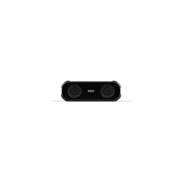
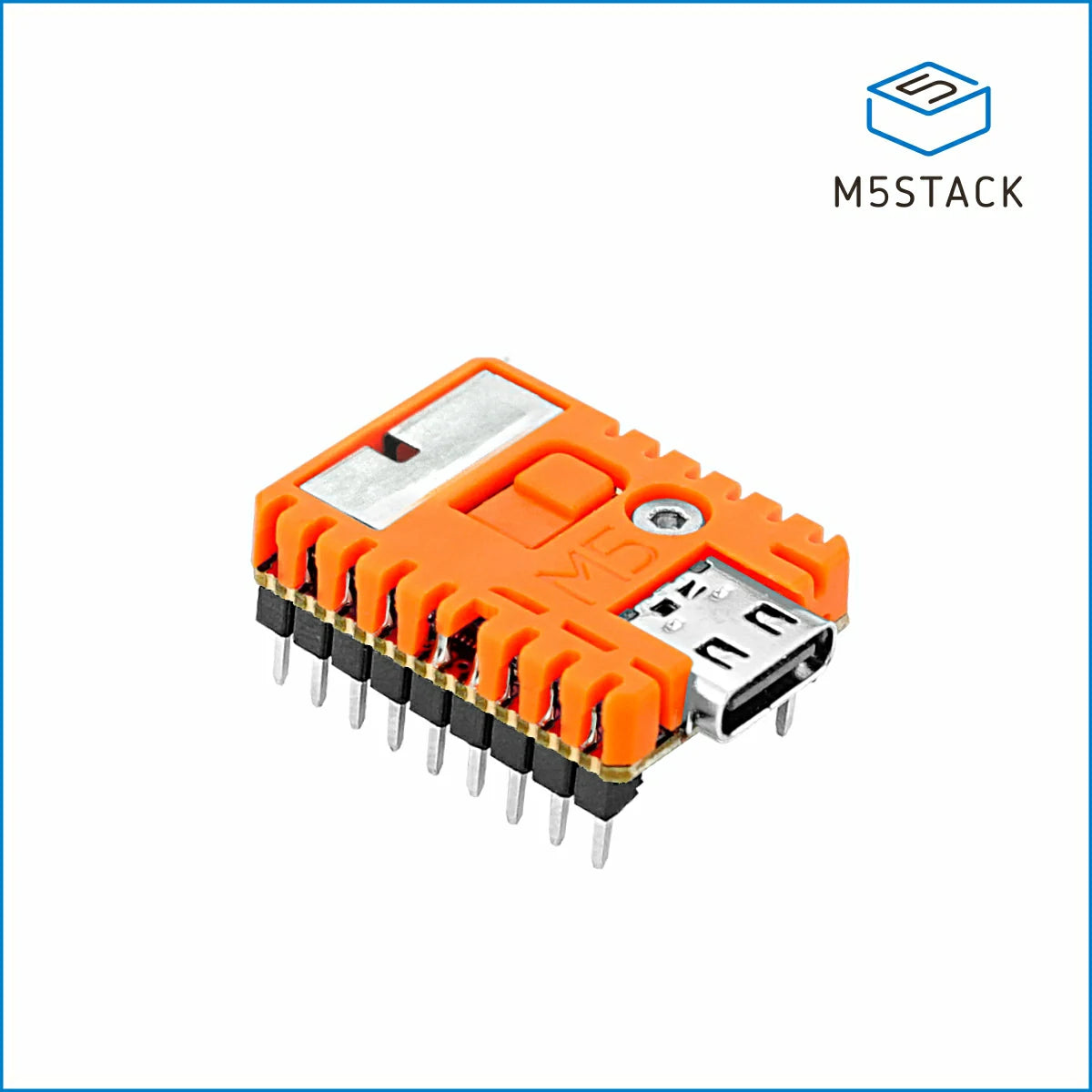
This is a complementary robot within the system, this is complemented with the wizard in order to provide more information to the system. This robot is built with a M5Stack (Figure 15) and a M5Stack-V (Figure 16), the latter has a KPU that allows us to use a mobilenet network to recognize objects.

Figure 15, M5Stack Core
Figure 16, M5Stick-V

Figure 16, M5Stick-V
Figure 17 shows the connection diagram between the M5Stakc-Core, M5Stick-V and PCA9685.
Figure 17, Connection diagram between M5Stack, V-Stick and Servo Controller

Figure 17, Connection diagram between M5Stack, V-Stick and Servo Controller
This robot is currently able to recognize emotional states using this network, allowing the classification of emotions using as development system the device M5StickV. In order to classify emotions, it was necessary to have a database in which the different wasmaciations have been divided into. The KDEF database (http://kdef.se/) was used to perform the training, this database has a total of 4,900 images of human facial expressions. The set of images contains 70 individuals showing 7 different emotional expressions.
Before starting the training phase, it is necessary to carry out a pre-processing phase, in which the images were resized. This is necessary because when using a mobilenet network architecture, the images must have a size of 224x224.
Windows 10 was used as the operating system in which the training phase was performed, this phase can be late between 3 and 4 hours (depending on the characteristics of the computer). Once the training is done, the system saves the *.h5 model, once you have this model it is necessary to convert it to the tensorflow lite *.tflite format. This is done using the command:
tflite_convert --keras_model_file " + keras_model_path + " --output_file " + tflite_pathAlready having our model *. tflite, the next thing is to transform it to *. kmodel. This is necessary because the KPIU of the M5StickV, only accepts models with this extension. This is done using ncc(https://github.com/kendryte/nncase/releases/tag/v0.2.0-alpha2).
ncc.exe -i tflite -o k210model --dataset " + path_all_dataset + " " + tflite_path + " " + kmodel_pathIn this step it is very important that all images in the dataset are in a single folder called a dataset.
At this point we must have something like this (Figure 17):

Figure 17, Model Structure
Once you have the model in *.kmodel format, you can access the model in two ways. The first one that uses SD memory in my case my M5StatickV no longer reads it :(, this can be done in the following way:
task = kpu.load("/sd/model.kmodel")Or we can use the Kflash_gui application and download the model to the address 0x300000, as shown in the following Figure 18.

Figure 18, Kflash Gui
Now we only need the micro pytho program, this was done using the maixpyide_2.3 development environment. The following is to convert our emotion classification code into boot.py, this is shown in the following Video 1.
Video 1 Emotion classification usin M5STICK-Vhttps://www.hackster.io/jarain78/emotion-classification-based-on-m5stickv-09c8e9
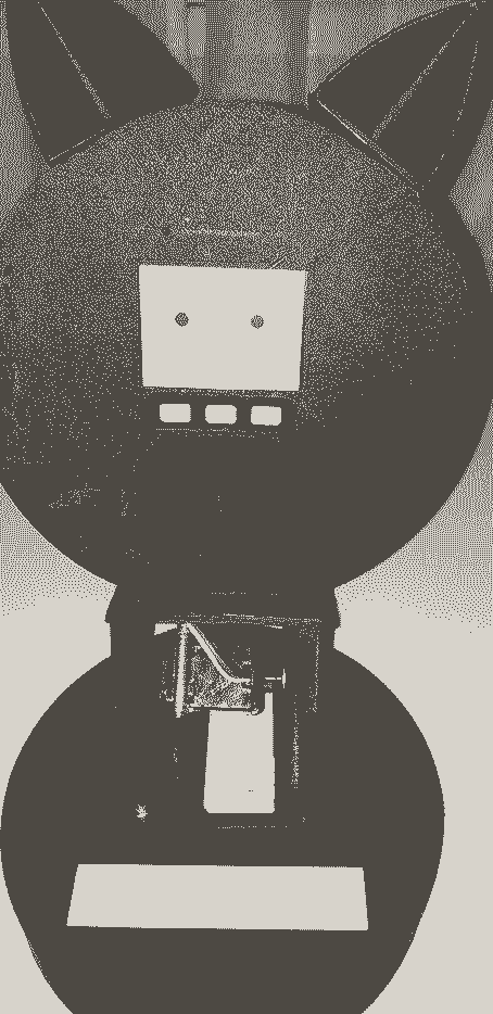
The Figure 17 shows the designed desktop robot:

Figure 17, Desktop Robot
The complete video is shown below:
Schematics, diagrams and documents
CAD, enclosures and custom parts
Code
Credits
Related products


Leave your feedback...