

Raspberry Pi Camera Flash Using Hexabitz Modules

Made by Aula_Jazmati
About the project
The purpose of this project is to get the best imaging whatever it is in the daytime or at night.
Project info
Difficulty: Moderate
Platforms: Raspberry Pi, STMicroelectronics
Estimated time: 1 hour
License: MIT license (MIT)
Items used in this project
Hardware components

View all
Story
In this project, we will build a light detector circuit using Hexabitz modules. The purpose of this project is to get the best imaging whatever it is in the daytime or at night.
The component that will allow us to detect light is a photoresistor. We will use a photoresistor's light-sensing ability to detect whether the circuit is exposed to darkness or bright light.
When exposed to bright light, we can make the modules do anything. For this project, we will turn on led module as night flash.

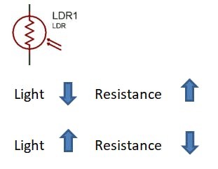
1- Photoresistors: Photoresistors, also known as light dependent resistors (LDR), are light sensitive devices most often used to indicate the presence or absence of light, or to measure the light intensity. In the dark, their resistance is very high, sometimes up to 1 MΩ, but when the LDR sensor is exposed to light, the resistance drops dramatically, even down to a few ohms, depending on the light intensity. LDRs have a sensitivity that varies with the wavelength of the light applied and are nonlinear devices.
1 / 2 • Three photoresistors with scale in mm

Three photoresistors with scale in mm

How to use a LDR
Photoresistors are found in many different applications and can be seen in many different electronic circuit designs. They have a very simple structure and they are low cost and rugged devices. They are widely used in many different items of electronic equipment and circuit designs including photographic light meters, fire or smoke alarms as well as burglar alarms, and they also find uses as lighting controls for street lamps.
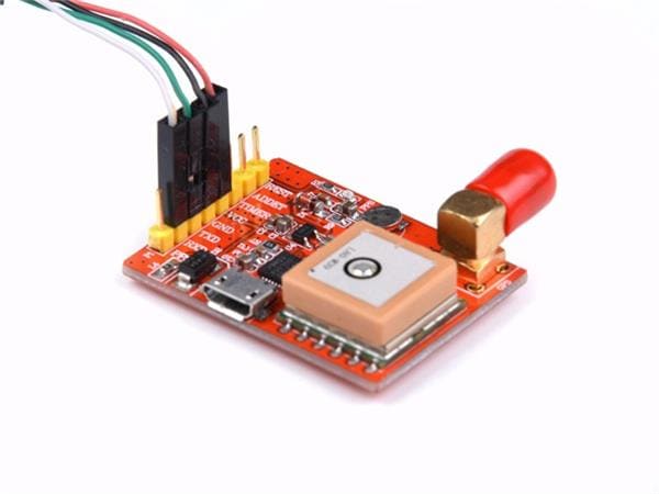
2- STLINK-V3MODS Programmer (H40Rx): H40Rx is a programmer module which contains STLINK-V3MODS stand-alone debugging and programming mini probe for STM32 microcontrollers (Hexabitz modules and other MCUs).
It supports the SWD (Serial Wire Debugging) interface for the communication with any STM32 microcontroller located on an application board.
It also provides bridge interfaces to several communication protocols, allowing for instance the programming of the target through bootloader.
STLINK-V3MODS Programmer (H40Rx)
")
STLINK-V3MODS Programmer (H40Rx)
3-Proto Board (H00R4x): H00R4x is a through-hole proto board module with 100-mil plated hole pattern. Use this module to prototype any circuit you want and add it to your Hexabitz collection! The module features a 1-mm plated drill pattern with 100 mil spacing. Six arrays and six power ports are available to seamlessly integrate with Hexabitz ecosystem. Power ports are separate from each other, in case you need multiple voltage rails in your array.
Hardware Design Files(EAGLE).
Proto Board (H00R4x)
")
Proto Board (H00R4x)
4-RGB LED (H01R0x): H01R0x is a smart RGB LED module based on Cree CLVBA-FKA RGB LED and STM32F0 MCU.
RGB LED (H01R0x)
")
RGB LED (H01R0x)
1 / 2 • OFF API

OFF API

ON API
5-Dual Coin Cell Battery Holders In-series (H04R2x): H04R2x is a compact coin-cell lithium battery holder that fits two CR2032 batteries in series. The output voltage is provided through Hexabitz SMD edge-pad connectors (3.3V on top and GND on bottom).
Dual Coin Cell Battery Holders In-series (H04R2x)
")
Dual Coin Cell Battery Holders In-series (H04R2x)
? Analog to Digital Conversion ?Microcontrollers are capable of detecting binary signals: is the button pressed or not? These are digital signals. When a microcontroller is powered from five volts, it understands zero volts (0V) as a binary 0 and a five volts (5V) as a binary 1. The world however is not so simple and likes to use shades of gray. What if the signal is 2.72V? Is that a zero or a one? We often need to measure signals that vary; these are called analog signals. A 3.3V analog sensor may output 0.01V or 2.99V or anything inbetween. Luckily, nearly all microcontrollers have a device built into them that allows us to convert these voltages into values that we can use in a program to make a decision.
Analog to Digital Conversion

Analog to Digital Conversion
An Analog to Digital Converter (ADC) is a very useful feature that converts an analog voltage on a pin to a digital number. By converting from the analog world to the digital world, we can begin to use electronics to interface to the analog world around us.
Not every port on a micro-controller has the ability to do analog to digital conversions. On the Hexabitz module, P2 & P3 pins can read analog voltages.
Read ADC value and percentage in P2 and P3 in all modules.

Read ADC value and percentage in P2 and P3 in all modules.
ADCs can vary greatly between micro-controller. Some microcontrollers have 8-bit ADCs (2^8 = 256 discrete levels) and some have 16-bit ADCs (2^16 = 65, 536 discrete levels).
The ADC on the Hexabitz is a 12-bit ADC meaning it has the ability to detect 4096 (2^12) discrete analog levels.
The way an ADC works is fairly complex. There are a few different ways to achieve this feat (see Wikipedia for a list).
Relating ADC Value to Voltage:
Analog to digital conversions are dependent on the system voltage.

Analog to digital conversions are dependent on the system voltage.
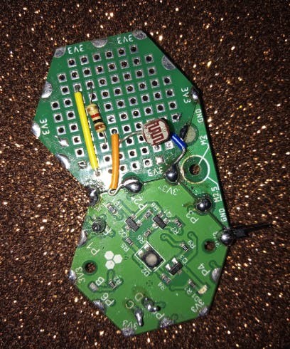
To show this in the real world let’s use the Hexabitz modules to detect an analog voltage. Use a light sensor, or simple voltage divider to create a voltage. Let’s setup a simple ldr circuit for this project:
LDR circuit diagram

LDR circuit diagram
LDR Module

LDR Module
The circuit of light detector with LDR is very simple and easy to build with very few components. As you can see in the LDR circuit diagram.
To start, we need to select ADC channel. To match the circuit diagram we will use P2:
void ADCSelectChannel (uint8_t ADC_port,char *side)
ADCSelectChannel API

ADCSelectChannel API
And then do the analog to digital version by using the ReadADCChannel API:
void ReadADCChannel (uint8_t Port,char *side,float *ADC_Value)
ReadADCChannel API

ReadADCChannel API
The value that is returned and stored in x will be a value from 0 to 4095. Hexabitz has a 12-bit ADC (4096 (2^12)).
And to reading the analog signal, & convert it to digital value as a percentage (0-100) you can use this API:
float GetReadPrecentage (uint8_t port,float *precentageValue)Note: Calling Get Read Percentage API will replace using ADCSelectChannel API, if it was called then the reading will be exclusively from the "bottom" layer.
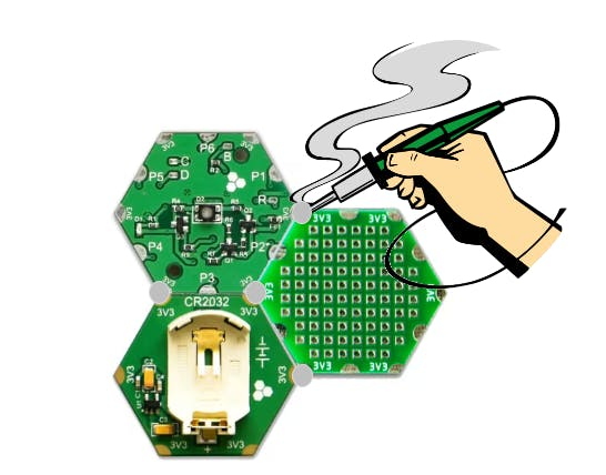
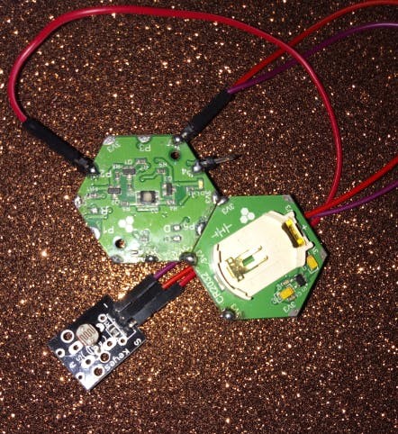
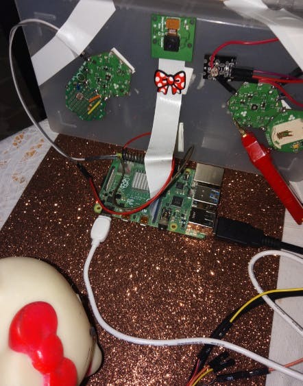
Steps ? 1) Plan the array and assemble the hardware:We prepare the project components and plan our array design by aligning modules side-by-side. Then we solder the modules together using Hexabitz Fixture.
1 / 2 • Project Array

Project Array
Check out this article for writing code with STM32CubeIDE.
First, we define our ADC variable in the main.c file of the module (H01R0x):
float x;To start, we need to select ADC channel. To match the circuit diagram we will use P2:
void UserTask(void *argument){

ADCSelectChannel(2,"top");
And then do the analog to digital version by using the ReadADCChannel API in the UserTask function, we write our repeated code that checks the amount of light.
If the ADC value is between 100 and 400 (dark) ?️ ? ? RGB LED module will be turn on ?
while(1){
ReadADCChannel(2,"top", &x);
Delay_ms(10);
if ( x > 100.0 && x < 400.0)
{
RGB_LED_on(99);
Delay_ms(100);
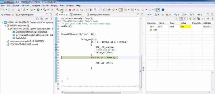
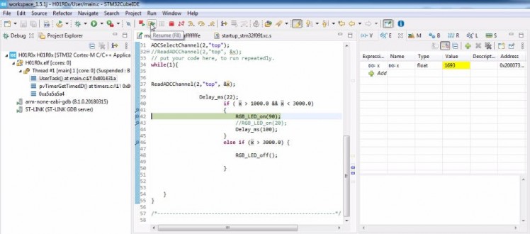
}If the ADC value is above 400 (light) ☀️, RGB LED module will be turn off.
else if (x > 400.0) {
			RGB_LED_off();
     				        }
}
This value was first monitored using the STM32CubeIDE debugging function to monitor ADC value live expressions, as shown in the screenshot:
1 / 3
These limit values change depending on the type of LDR so they should be checked when a different LDR is used.
1 / 2
1 / 2


Please feel free to leave a comment here if you have any questions or concerns regarding this project ?
Schematics, diagrams and documents
Code
Credits
Related products


Leave your feedback...