

Prototyping The Future: Building A “star Trek” Tricorder

Made by mbparks
About the project
As an engineer, their concepts for yesterday's entertainment franchises serve as today's blueprint for real-world innovation.
Project info
Difficulty: Difficult
Estimated time: 2 weeks
License: GNU General Public License, version 3 or later (GPL3+)
Items used in this project
Hardware components


View all
Story
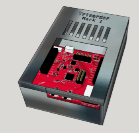
Figure 1: The concept image for the “Tricorder” made from a TI Launchpad featuring the new MSP432 and several environmental sensors.
Summary
The majority of the world is aware of names like Picasso, Van Gogh, and Renoir - but for me, the science fiction concept art of Ralph McQuarrie (Star Wars) and Matt Jeffries (Star Trek) is every bit as gorgeous and perhaps more important. As an engineer, their concepts for yesterday's entertainment franchises serve as today's blueprint for real-world innovation.
One such 21st century innovation is the brand new Texas Instruments MSP432 LaunchPad. Extremely powerful and extremely energy efficient, these new microcontrollers are perfect for turning science fiction into science fact. Coupled with an array of powerful, low-cost sensors we set out to build the prototype “Star Trek" Tricorder today knowing what its fictional descendant will look like in the 23rd century. Essentially, our "Tricorder" is an environmental sensing device that measures the presence of oxygen, magnetic field, ambient light, humidity and temperature.
Overview
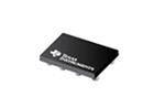
The new MSP432-based LaunchPad is the core of our project, specifically with the new MSP-EXP432P401R processor. These new LaunchPads pack quite the computing punch, perfect for our Tricorder project. Some highlights include:
- 48MHz 32-bit ARM Cortex M4F with Floating Point Unit and DSP acceleration
- Analog: 24Ch 14-bit differential 1MSPS SAR ADC, Two Comparators
- Memory: 256KB Flash, 64KB RAM
- Timers: 4 x16-bit, and 2 x 32-bit
- Communication: Up to 4 I2C, 8 SPI, 4 UART
- 40 pin BoosterPack Connector, and support for legacy 20 pin BoosterPacks
It should be noted that while the new 40-pin BoosterPack connector can support the new legacy 20-pin connectors physically, that some functionality has been moved around. As always, download and read the user guides before using a new board or BoosterPack. For example, I originally intended to use the two capacitive touch buttons on the Sharp96 display BoosterPack as the buttons for the user interface (UI). While the Sharp96 (which was originally built for older MSP430-based LaunchPads) will physically plug into the new MSP432 LaunchPad, two pins used by the Sharp96 for the left capacitive button are now the hardware I2C pins on the MSP432P401R. Please note, the Tricorder BoosterPack will only support the newer 40-pin based connectors.
While there are some compatibility issues, these can be easily corrected with revisions to a BoosterPack design. This small inconvenience is more than made up for by the ability to utilize drop-dead easy multitasking (MT). The Energia IDE, which will be using to code the software for the Tricorder, has been updated to allow newer MSP432 microcontrollers to leverage the TI-RTOS to allow for the creation of multiple “parallel” tasks by simply creating a different .ino file for each task. We put “parallel” in quotes because there are no multiple cores running truly in parallel; rather, we are relying on the TI-RTOS and Energia to give us the results that we would expect as if we were running multiple hardware processing cores. In short, it makes running multiple concurrent tasks much, much easier. Inter-process communication is achieved through the use of global variables.
The HDC1000 Digital Humidity Sensor
The first sensor we’ve included is the HDC1000, which can detect humidity levels. It comes in a tiny 2.1mm x 1.6mm, 8-bump DSBGA package. It operates on 3V to 5V and relies on an I2C interface to the microcontroller. The HDC1000 offers a 14-bit measurement resolution and a relative humidity accuracy of ±3%.
The I2C address is 0x40 be default. After startup the HDC1000 requires 15ms before it can begin to report humidity readings. Humidity measurements can be found in the 16-bit 0x01 register. All data bytes are transmitted MSB first. The humidity measurement itself is 14-bits, with the two lowest significant bits of the humidity register being reserved and always set to 0.
To calculate the relative humidity (%), you can apply the following formula:
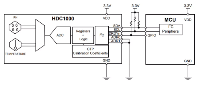
Figure 2: The HDC1000: shown is a typical application wiring diagram from the HDC1000 data sheet. The HDC1000 is a digital RH&T sensor with excellent measurement accuracy at very low power, with a 200 nA sleep mode current. No worries; the HDC1000 are factory calibrated.
The LMT70 Precision Analog Temperature Sensor
We’re demonstrating two devices with temperature sensing capabilities on the Tricorder: the above HDC1000, and this LMT70, for a couple of reasons. In general, analog temperature sensors are a bit cheaper than digital temperature sensors, and if you have an application that is low on digital inputs, it’s always good to know how to use an analog input if that’s all you have left to work with. The other major difference is that a digital signal operates using discrete signals or steps, which makes it less susceptible to noise than analog signals. Analog design in general is more complicated, as well. For most applications, however, a digital sensor is going to provide the same information as an analog signal. The Tricorder has both so you have the opportunity to evaluate both. For some designs, footprint and/or cost is paramount, and so tradeoffs can sway choices either way. If you can think of another reason why one might want to use analog over digital (besides the application requiring it, like in many RF designs) please tell us in the comments section.
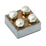
The LMT70 precision analog temperature sensor comes in a 0.88mm x 0.88mm DSBGA - WLCSP package. The LMT70 provides an analog output that has an accuracy of ±0.36°C over an operating range of −55°C to 150°C. The supply voltage can range from 2.0V to 5.5V with a typical current draw of a mere 9.2 µA, and 12 µA maximum.
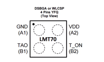
Figure 3: There are just four pins on the LMT70: GND is ground reference for the device, VDD is supply voltage, TAO is the temperature analog output pin, and T_ON is active high input. If T_ON=0, then the TAO pin output is open. If T_ON=1, then the TAO pin is connected to the temperature output voltage. For more information see the Texas instruments data sheet for the LMT70.
Unlike the HDC1000, the LMT70 temperature sensor does not use the I2C protocol. Instead, it relies on two microcontroller pins; one GPIO pin and one analog input pin. One connects to the T_ON pin of the LMT70. When T_ON is driven high, it enables a temperature-varying analog output voltage on the pin TAO. The LMT70 requires 0.6ms from the time power is applied before the final voltage on TAO is achieved. Similarly, the TAO requires 30µs to stabilize after T_ON is driven high.
To calculate the temperature value, the following equation can be used if the expected temperature range is -10C and 110C:
TM = a(VTAO)3 + b(VTAO)2 + c(VTAO) + d
where:
a = -1.809628E-09
b = -3.325395E-06
c = -1.814103E-01
d = 2.055894E+02
VTAO is measured in mV. TM is measured in degrees Celsius.
To convert to Fahrenheit use the formula TF = [(9/5) * TM] + 32.
The OPT3001 Ambient Light Sensor
For the ability to detect ambient light intensity, we’ve included the OPT3001 optical sensor, which measures the intensity of visible light as visible to the human eye. The OPT3001 is a single-chip lux meter which can mimic the human eye’s reaction in measuring the intensity of light; and it outputs a signal proportional to the amount of visible light incident upon the Sensor. No external components are required for the OPT3001 to operate, however a filtering capacitor is included across the Vcc and ground pin.
Both the inputs and outputs of the OPT3001 communicate over the I2C bus. The address of the sensor is set at 0x44, and all data bytes are transmitted most-significant bits first. The OPT3001 can be configured to run in an automatic mode, where it always selects the optimal full-scale range settings for the given ambient lighting conditions. The OPT3001 can be configured to operate continuously or in a power-sipping, single-shot measurement mode. The result register is 0x00 and the configuration register 0x01; both are 16-bits wide. The result register contains a 4-bit exponent ( RR[15:12] ) and 12-bit mantissa ( RR[11:0] ).
To translate the contents of the results register into a lux value, use the following equation:
lux = 0.01 * (2RR[15:12]) * RR[11:0]
The OPT3001 can be placed into automatic full-scale-range setting mode by setting the configuration register range number field (RN[3:0]) to 1100b. The first measurement that the OPT3001 takes when placed in the auto-range mode is a brief assessment measurement used to determine the appropriate full-scale range. After the calibration is complete, the OPT3001 takes its first actual measurement. As a way to help visualize the lux unit of measure, remember that 1 lux is the equivalent to the amount of light received 3 feet from a single candle.
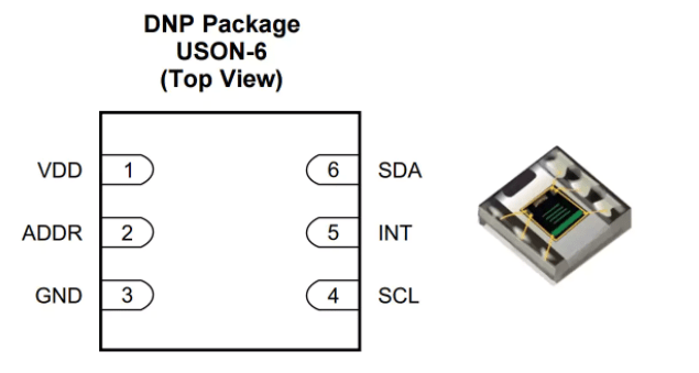
Figure 4: Pin-out of the OPT3001 on the left, with a peek under the package cover of the OPT3001. Source: OPT3001 datasheet and TI product page.
The MAG3110 Magnetometer
What would a Tricorder be without a magnetic field sensor? After all, the earth’s magnetic field (the magnetosphere) is what shields us from solar radiation and enables our atmosphere to remain intact over the long term. The magnetosphere is also what makes compasses and this magnetometer work.

Figure 5: "A magnetosphere is that area of space, around a planet, that is controlled by the planet's magnetic field. The shape of the Earth's magnetosphere is the direct result of being blasted by solar wind, compressed on its sunward side and elongated on the night-side, the magnetotail." – nasa.gov/mission_pages/sunearth/multimedia/magnetosphere2_prt.htm. Credits: NASA.gov
With the addition of the Freescale MAG3110, the Tricorder gains the ability to detect magnetic fields. The MAG3110 is a three-axis magnetometer in a tiny 2mm x 2mm form factor. Magnetometers are often used as embedded digital compasses in many products. The full scale range of the magnetometer is ±1000μT, with a sensitivity of 0.10μT/LSB.
The I2C address of the MAG3110 is 0x0E. The magnetic field along each axis is measured as a 16-bit number, which in turn is split into a high and low register of 8-bits each. Therefore to measure each axis, you most poll a total of 6 registers as follows:
X-axis MSB (OUT_X_MSB): 0x01
X-axis LSB (OUT_X_LSB): 0x02
Y-axis MSB (OUT_Y_MSB): 0x03
Y-axis LSB (OUT_Y_LSB): 0x04
Z-axis MSB (OUT_Z_MSB): 0x05
Z-axis LSB (OUT_Z_LSB): 0x06
To cut down on power consumption, the Tricorder will rely on the triggered measurement mode of operation. Per the MAG3110 datasheet/user guide, a measurement is taken as follows:
1. Enable automatic magnetic sensor resets by setting bit AUTO_MRST_EN in CTRL_REG2. (CTRL_REG2 = 0x80)
2. Initiate a triggered measurement by writing 0b00011010 to CTRL_REG1 (CTRL_REG1 = 0b00011010).
3. MAG3110 will acquire the triggered measurement and go back into STANDBY mode. It is possible at this point to sync on INT1 or resort to polling of DR_STATUS register to read the acquired data out of MAG3110.
The MAG3110 can take a new reading every 12.5ms.
The LMP91000 Electrochemical Sensor Interface
The LMP91000 is not a sensor itself, but rather it’s an integrated circuit that allows a microcontroller to easily interface with electrochemical sensors such as the Alphasense O2-A1 oxygen sensor. Electrochemical gas sensors work by oxidizing a target gas at an electrode and producing a corresponding electrical current. The LMP91000 then measures this resulting current and produces a corresponding output voltage that can be read directly by a microcontroller’s ADC pin.
A key advantage of technology used electrochemical sensors is the output current is linearly proportional to the gas concentration. However electrochemical sensors are tailored for specific gases, thus requiring different sensors for different gases.
The LMP91000 supports both 3-lead amperometric sensors and 2-lead galvanic cell gas sensors. The three leads used in electrochemical sensors (Counter, Worker and Reference) has been broken out to a set of header pin for the developer to interface whichever sensor they choose. Configuring the gain of the LMP91000 is done over the I2C bus, the device’s address is 0x90. In addition, the MENB pin needs to be held low during the whole I2C communication.
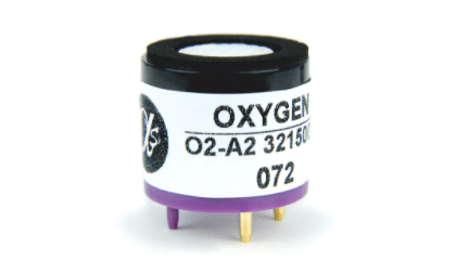
Figure 6: LMP91000 works with a gas sensor, in this case we used the Alphasense oxygen sensor. Once we measure oxygen in sufficient quantities in an alien atmosphere, we can take off space helmets and boldly go where no one has gone before...
The PGA900 Programmable Resistive Sensing Conditioner
Similar to the LMP91000, the PGA900 itself is not sensor. It serves as an interface for resistive bridge sensors such as a Honeywell NBP pressure sensor. Resistive bridge sensors trace their beginnings to Wheatstone bridge circuits which we used to make highly accurate resistance measurements without the need for accurate voltage sources. The PGA900 onboard the Tricorder BoosterPack has been configured to interface with a Honeywell NBP pressure sensor with voltage output. The internal configuration of the NBP pressure sensor is a resistive bridge in which the resistance of one of the branches varies with pressure. Fluctuations in pressure will result in changes in the voltage measured across the LMP91000 pins VINPP and VINPN. The two RC low pass filters (tuned for 106 Hz cutoff) should be placed in between the output of the pressure sensor and the VINPP and VINPN leads.
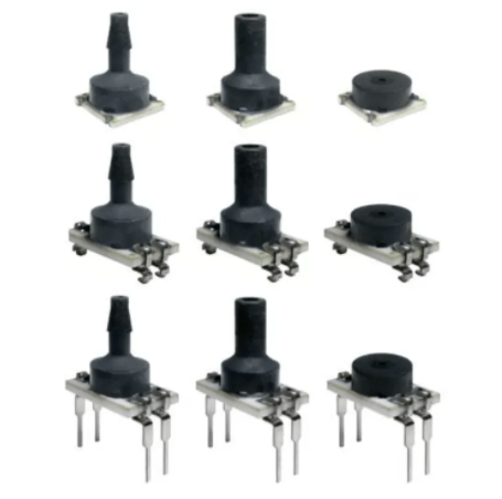
Figure 7: The Honeywell NBP Series Board Mount Pressure Sensors are uncompensated, unamplified sensors that measure absolute and gauge pressures. They are intended for use with noncorrosive, non-ionic gases.
For the Tricorder BoosterPack the CSN pin has been grounded, setting it to a Logic 0. Thus the device’s I2C memory page addresses are 0x40:0x47, the complete listing is as follows:
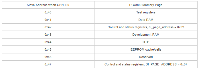
The PGA900 has a 14-bit digital-to-analog converter (DAC) that will produce a ratiometric output voltage with respect to the VDD supply. Ratiometric mode is achieved by setting the DAC_RATIOMETRIC bit in DAC_CONFIG. For the Tricorder BoosterPack the DAC gain amplifier will be configured to operate in voltage amplification mode. Though the PGA900 is capable of operating in current amplification mode for 4- to 20-mA applications.
The DAC gain can be configured for a specific gain value by setting the DAC_GAIN bits in DAC_CONFIG register. The final stage of DAC gain is connected to supply voltage and ground which gives the PGA900 ability to drive VOUT voltage close to VDD voltage which can be fed into an ADC pin on the MSP432.
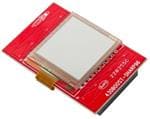
The Sharp® LCD BoosterPack for the LaunchPad
The Sharp96 LCD display was selected since it comes in a ready-to-use BoosterPack and offers very good low power performance. The Sharp96 is based on an LCD technology called Silver Metallic Polymer Network Liquid Crystal (PNLC). It is 1.35-inch display offering 96 x 96 pixels that can be controlled over the SPI bus. With typical power use of only 10 µW, the display is still visible in a low light setting (0.5 lux, by comparison a typical evening twilight is about 10 lux) without the need for a backlight. In addition, with a 50% reflectance the display will be nice and sharp outdoors as well.
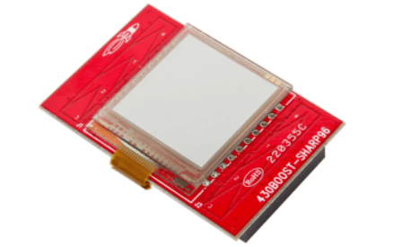
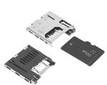
Figure 8: The 430BOOST-SHARP96 Sharp LCD BoosterPack is the display used for the Tricorder. It is 1.35-inch display offering 96 x 96 pixels that can be controlled over the SPI bus.
The Sharp96 LCD display will be our primary interface with the Tricorder BoosterPack. It will be displaying all the readings that our sensors are pulling in by measuring the environment.
System Build Up
The Tricorder BoosterPack has been built to provide some flexibility in terms of hardware tweaks by the user. The Pmod interface and breakout headers for the LMP91000 and PGA900 will let the user test a wide variety of sensors of their choice.
In terms of software, the systems is very modular and adding additionally functionality should be quite straightforward for anyone with a basic understanding of C or C++ programming.
Expanding Functionality: How to add additional sensors to the Tricorder BoosterPack using the Pmod interface
The Peripheral Module (Pmod) interface is a specification managed by Digilent Inc. Similar in concept to the USB specification, but instead of handling high-speed data, Pmod serves as a standard, low-level interface between sensors and a microcontroller. For more information about the Pmod specification visit the Digilent website.
The Tricorder BoosterPack Pmod interface follows the Type I GPIO Interface specification provided by Digilent. This version of the Pmod interface provides access to four GPIO pins, 3.3V or 5V, and ground.
The four Pmod GPIO pins are tied to the following pins on the MSP432P401R LaunchPad:
Pmod 0: Pin 11 (P3_6)
Pmod 1: Pin 32 (P3_5)
Pmod 2: Pin 33 (P5_1)
Pmod 3: Pin 34 (P2_3)
In addition to the four GPIO pins there are pins for power and ground. The power pin can provide 3.3V or 5V depending on the position of the switch atop the Tricorder BoosterPack.
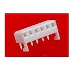
For custom built peripheral boards, the only requirement is to include 6 right angle male headers in order to plug into the Pmod host interface on the Tricorder BoosterPack.
Adding a Third Party Pmod Peripheral Device in Software
Building a Pmod peripheral board is only half the solution. The demonstration could will also have to be tweaked to incorporate the new sensor.
First increment the numSensors value to account for a new sensor:
#define numSensors 6
Next, under the “initialize sensors” portion of the code, a new entry will have to be made for the new Pmod sensor:
- // Initialize sensors and data fieldstricorderSensor[HDC1000_id].sensorID ="HDC1000";tricorderSensor[HDC1000_id].UM = "% Humidity";tricorderSensor[HDC1000_id].sensorVal = -1;tricorderSensor[LMT70_id].sensorID ="LMT70";tricorderSensor[LMT70_id].UM = "Degrees F";tricorderSensor[LMT70_id].sensorVal = -1;tricorderSensor[OPT3001_id].sensorID ="OPT3001";tricorderSensor[OPT3001_id].UM = "Lux";tricorderSensor[OPT3001_id].sensorVal = -1;tricorderSensor[MAG3110_id].sensorID ="MAG3110";tricorderSensor[MAG3110_id].UM = "uT";tricorderSensor[MAG3110_id].sensorVal = -1;tricorderSensor[LMP91000_id].sensorID ="O2 Sensor";tricorderSensor[LMP91000_id].UM = "ppm";tricorderSensor[LMP91000_id].sensorVal = -1;tricorderSensor[PGA900_id].sensorID ="Pressure";tricorderSensor[PGA900_id].UM = "kPa";tricorderSensor[PGA900_id].sensorVal = -1;
The data structure consists of the three parts:
- tricorderSensor[x].sensorID: The name of the sensor
- tricorderSensor[x].UM: The unit of measure the sensor will be reporting
- tricorderSensor[x].sensorVal: The value of the sensor’s output, default should be -1
Lastly, a library for the sensors needs to be included to handle the low level communication and control of the sensor. Refer to the “Expanding Functionality” section above for the list of the Pmod GPIO pins that will be needed for the library.
Assembly
Operating the Tricorder
We printed a nice little case to give us the Tricorder look-and-feel. But this is completely optional if you just wish to use the BoosterPack as a development board to access the various sensors.
Construction is pretty straightforward.
1. Hookup the MSP432 LaunchPad to your computer with the provided USB cable and launch Energia. Then upload the provided software. Unplug the USB cable from the LaunchPad.
2. Attach the Tricorder BoosterPack onto the LaunchPad.
3. Next attach the Sharp96 LCD display BoosterPack into the Tricorder BoosterPack. The old 20-pin configuration of the Sharp96 BoosterPack means it should plugin to the outer headers pins on the Tricorder.
4. Lastly, plugin the USB cable back into the LaunchPad board and watch the Tricorder come to life.
5. Using the buttons on the bottom of the Tricorder BoosterPack, the user can navigate through the various sensor readings.
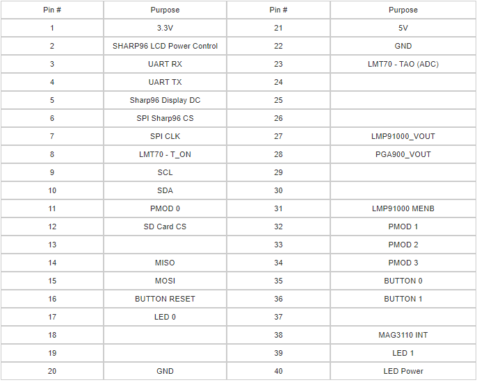
Table 2: Tricorder BoosterPack Pin Map
Project in Action
Launching the Future
We’ve really only scratched the surface of what’s possible with the MSP432-based LaunchPad. What device from the realm of science fiction would you attempt to turn into reality using these new LaunchPads?
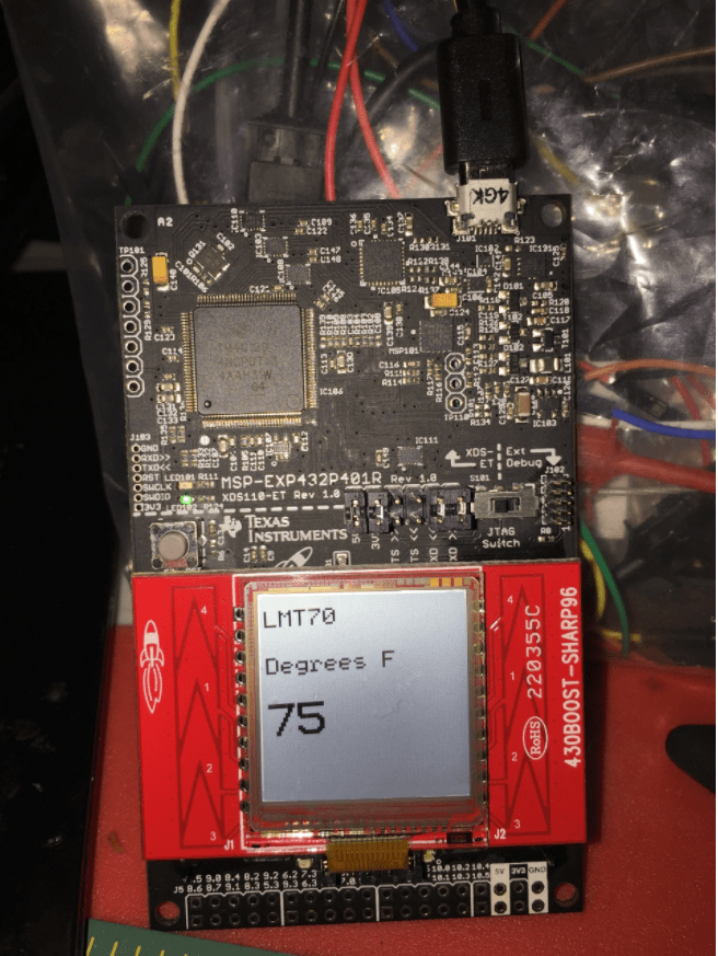
Figure 9: The Tricorder, shown without the case.
Credits
mbparks
Mike Parks is the owner of Green Shoe Garage, a custom electronics design studio and security research lab located in Southern Maryland. He produces content for the Gears of Resistance which shares news and tips for those interested in the maker movement, open-source hardware and software, STEAM education, citizen science, and digital citizenship. He is also an extra class ham radio operator, a licensed Professional Engineer in the state of Maryland, and most notably a dad.
Related products


Leave your feedback...