
Open Source Desktop Synthesizer

Made by The888Timer
About the project
The desktop synthesizer uses an Intel Arduino 101 to turn a small box and some conductive strips into a musical instrument.
Project info
Difficulty: Difficult
Estimated time: 2 weeks
License: GNU General Public License, version 3 or later (GPL3+)
Items used in this project
Hardware components

View all
Hand tools and fabrication machines
Story
Summary
The desktop synthesizer uses an Intel Arduino 101 to turn a small box and some conductive strips into a musical instrument.
The musically-inclined and the technologically-minded both share a penchant for creative expression. A good number of engineers are musicians, and there are a wealth of do-it-yourself musical instruments all over the internet. Musical instruments are awesome, but they can be expensive. When I first learned about open-source hardware, I immediately got the idea to make an instrument.
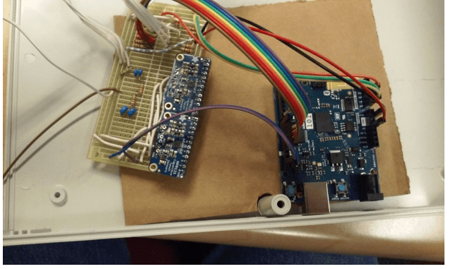
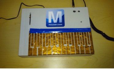
Inside the desktop synthesizer - Intel Arduino 101, custom circuit board, and dual Adafruit MPR121s
When I hear digital electronics and music in the same sentence, I think of synthesizers. The analog synthesizers of the 70s and the digital ones from the 80s onward use electronics to make music unreproducible by acoustic instruments. They often use the piano keyboard, which is one of the most universal interfaces in the music world. With the power of a microcontroller and a few simple components, I realized that I could make my own quirky and customizable synthesizer that anyone could play. This project uses the Intel Arduino 101 as my microprocessor and a couple of Adafruit MPR121 Capacitive Touch Sensor breakout boards.
Materials
The enclosure and prototyping board you use are up to you. I have listed the ones I chose above as the pictures in the “Assembly” section show in detail how I arranged everything on the protoboard. When everything is wired up, you could throw your project in a shoebox and play it with the keys taped on the lid. I put my project in a Hammond enclosure made of ABS plastic for durability, but any box with similar dimensions will do. The Hammond enclosure measures approximately 280mm x 199mm x 76mm and there was plenty of room.
Overview
The general design of the synthesizer has three major sections: inputs, output, and peripherals.
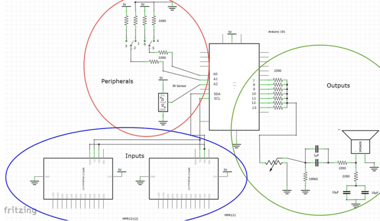
Figure 1: The schematic, made with Fritzing. See Resources for a higher-res version, as well as the original Fritzing file.
The first section is Inputs, circled in blue above, which consists of two of Adafruit’s MPR121 breakout boards. By wiring each channel of the breakout board to a conductive material (copper, in our case), we will create a piano keyboard, the universal musical human interface.
The second section is Peripherals, circled in red, which includes the Vibrato Sensor and the Mode Switch. Both of these devices send data to the Arduino 101 to change the sound of the keys. The Vibrato sensor allows the user to bend the pitch of the notes they are playing, from a light vibrato to a deep bass drop, all achieved by simply waving a hand in front of the sensor. When the user raises their hand, the pitch increases until it hits a maximum; when they lower their hand, the pitch drops to a rumbling bass pitch.
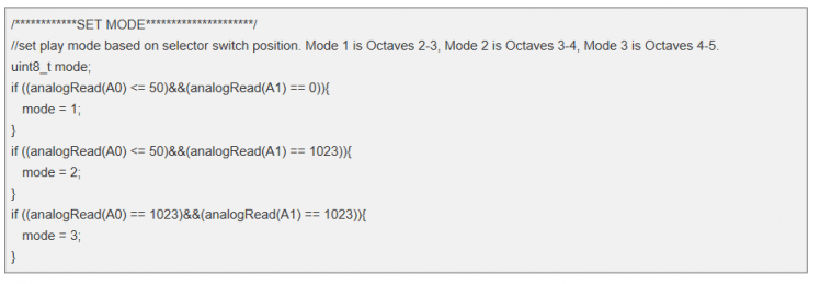
The Mode Switch changes which octaves the 24 keys cover:
The high octave in Mode 1 is the same as the low octave in Mode 2, while the high octave of Mode 2 is the low octave of Mode 3. The octaves overlap for a total of 4 octaves.
The final section is Outputs, circled in green. Really, there is just one output, but the Arduino outputs 7 separate signals (one for each note currently being played) which are summed in the output circuit, adjusted with the volume potentiometer, run through a high- and low-pass filter, and sent to a ¼” phone output. You can plug a ¼” to 1/8” adapter into the output to play the synth through your headphone, or you can use an instrument cable to plug into an amplifier.
Software
You can download the full sketch for this project here on GitHub. You can use the free Arduino IDE to program your board. Copy and paste this code into the IDE and upload it to your Arduino. If you have never used the Arduino 101, or any Arduino board, please refer to Arduino’s Getting Started page for setting up your IDE. If you are interested in how the program works, you can continue reading below about each section.
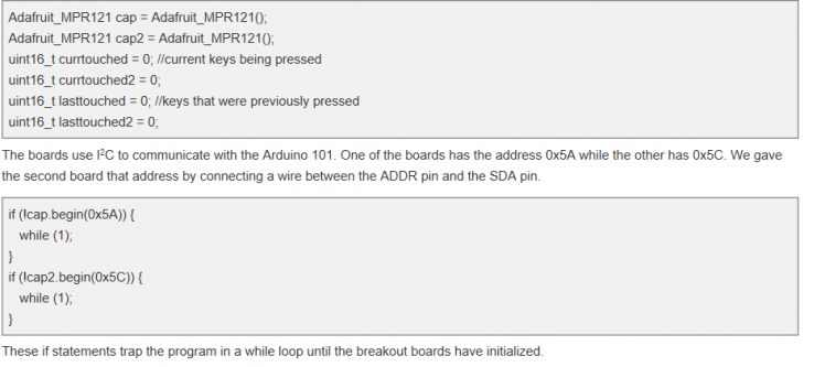
The MPR121 Adafruit Library
The capacitive touch sensors run on a library written by Adafruit. Instructions on how to download and install the library can be found on Adafruit’s website. You must install the library for the touch-capacitive keyboard to work properly.
This library sets a baseline capacitance and senses when one of the pins on the MPR121 breakout board is touched. Any program using the boards must include the library header and Wire.h. The example program that comes with the library details how to use the library. The part of the synth code that deals with this library is heavily based on Adafruit’s example program, yet it’s also doubled to account for the use of two breakout boards. The use of the ‘current touched’ and ‘last touched’ variables, one for each of the breakout boards, will be explained in the next section.
Keys and Pins Explanation
There are two major steps in the program’s handling of the key inputs: the reading of the keys and the assignment of the pins. The program reads the keys and decides which notes need to be played. Then the program checks all of the digital output pins (pins 7-13), picks the next available pin, and assigns the new note to a pin. The pin plays this note and gets added to all of the other notes by the summing circuit on our protoboard. Now, in more detail:
The program first reads the capacitive touch sensors and puts them the variables “currtouched” and “currtouched2”.
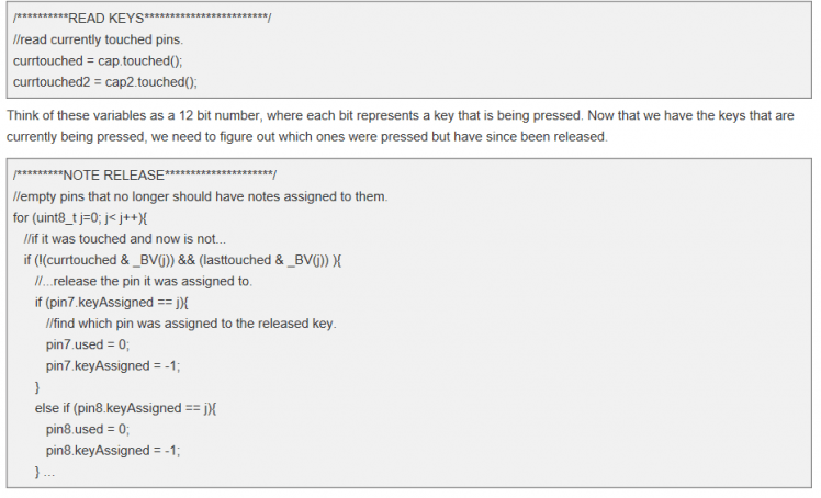
I used a series of nested if-then statements inside of a for-loop to figure out which notes that used to be pressed are now not being pressed. This is done by comparing a particular bit in the “currtouched” variable with the same bit of a variable called “lasttouched.” I used “& _BV(j)” to mask the variables to compare one bit at a time, where j is the incremented variable in the for-loop. Basically, we check one bit at a time.
In the case that a key has been released, we then have to find out which pin that key was assigned to. The keyAssigned variable in each pin struct will tell you which key activated that pin. Releasing a note (stopping that note from playing) is as easy as setting the used variable to 0 and assigning that pin a key of -1.
Regarding the “pin struct”, I will now outline each of the variables and what they do. If you are not familiar with the concept of a “struct” in C/C++, check out this tutorial on data structures. I made the pin_t datatype to hold all of the important information about the pins in a way that I could refer to them in the program wherever I wanted to.
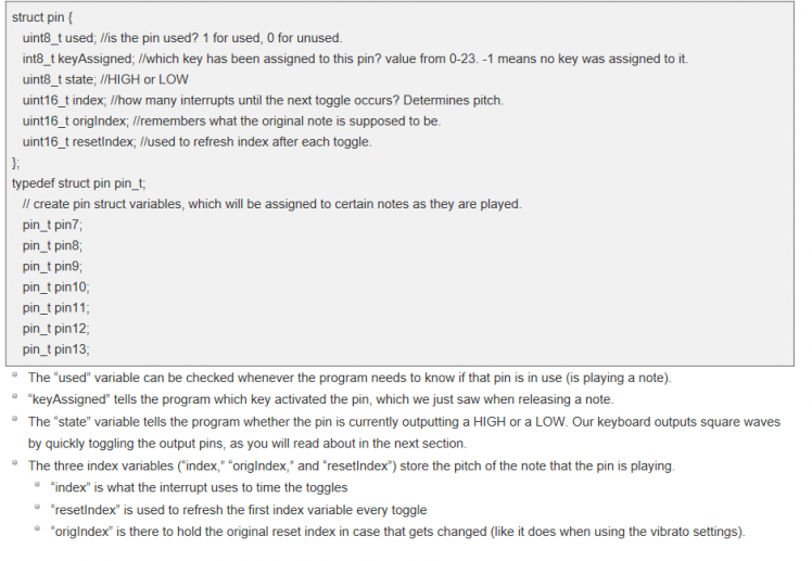
This will make more sense later, as I go into more detail about why we have different index variables in the later sections.
Once the old notes are released, we have to take a look at keys that may have been pressed since the last cycle.
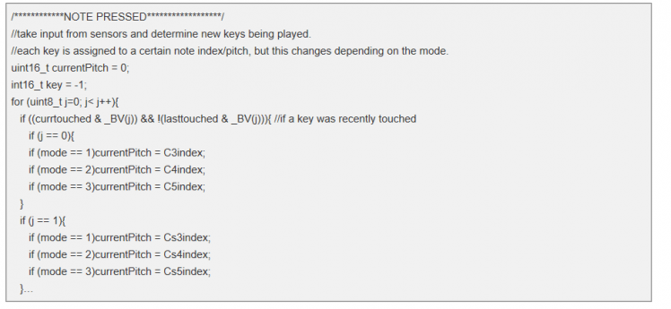
The structure of the index assignment is very similar to the note release code except instead of changing the “pin struct” variables, we are changing a variable called “currentPitch” depending on the current key pressed and the mode the system is in.
At the top of the sketch there is a large lookup table of index values which I chose based on a formula, with a little tweaking to account for tuning. Each note from C3 to B5 has an index that tells the program how many interrupts to wait before the program should toggle the pin. This section checks which key has been pressed and loads up the currentPitch variable with the appropriate index.

The notes currently being touched are then saved in the “lasttouched” and “lasttouched2” variables. We do this so on the next cycle the program can comparing the pressed keys with what was previously pressed and change the pins appropriately. The key that has been assigned is also remembered by writing this into the variable “key”.
The final step of note processing is pin setting.
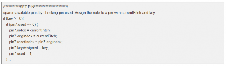
This step first checks that some change has occurred (by checking that “key” is not negative), then it checks which keys are not being used. As soon as it finds an unused key, it assigns the three index variables the “currentPitch,” tells the pin which key activated it (via the “keyAssigned” variable) and marks the pin as “used.”
The Interrupt and Pin Toggling
Now that each pin has an index assigned to it, we can talk about the interrupt service routine.
The actual sound is created by rapidly toggling the output pins on and off, creating a square wave. Each pin can only support one note at a time, which is why I assigned each note to a different pin. If there were seven different timers on the Curie module, you could simply set the pins to toggle at different speeds by assigning them each a timer, but there is one timer available for use: CurieTimerOne.
So we have to set CurieTimerOne to an extra fast interrupt and toggle the pins at various times on that interrupt. This is where the indexes become useful. Each note has its own index, or amount of interrupts that happen between toggles, for the note created to be at that exact pitch. So we set the interrupt to occur every 4 microseconds:

From here on out, the interrupt will be constantly occurring, calling the function I have created called “interruptHandler.” The first thing interruptHandler does is check if a pin is currently being used. It does this for every pin.
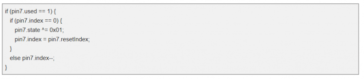
If the pin is being used, it then checks the pin’s index. If the index has hit 0, it means it is time to toggle the pin (i.e., half a period has lapsed since the last toggle). The toggle uses an exclusive-or (XOR) operator to toggle the pin’s state, then resets the index to prepare it for the next interrupt. If the pin’s index has not hit zero (which is true most of the time) the index will decrement.
After the index has been assessed, the Interrupt Handler program must actually do the work of toggling the pin. Thus far, we have changed the pin’s state variable, but we have not actually affected the pin. So, at the end of every interrupt service routine, we use the digitalWrite function on each pin:

Interrupt service routines have to happen quickly or they will interfere with the flow of the program. So we let the main loop handle the major administrative duties like assigning pins and recognizing key presses, and let the interrupt do the dirty work of changing the pins.
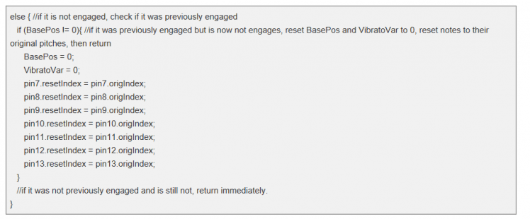
The Vibrato System
The vibrato system alters a pin’s reset index to temporarily change the pitch of a note. How much that pitch is altered is determined by the distance the IR sensor reads. To do this, we will utilize two static variables, “BasePos” and “VibratoVar.”
The CheckVibrato function first makes sure that there is a hand in front of the IR sensor, reading analog pin A2 and checks if it has a value greater than 110 (the closer an object is to the sensor, the higher the number returned). If a hand is in front of the sensor, the vibrato is considered “engaged.”
Once the sensor is engaged, the program figures out if it was previously engaged. If not, a new “base position” has to be recorded. The base position is the first position that the user’s hand was in when it entered the sights of the IR sensor; holding your hand here keeps the pitch at its original frequency.
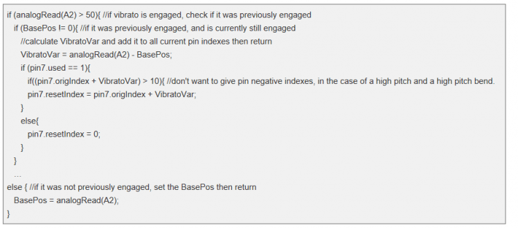
Once the base position has been recorded, the program waits until the current cycle comes back again to change the pitch. On this second pass, the program recognizes that the vibrato was previously engaged (it sees that BasePos is not equal to 0) and sets a new benchmark: “vibrato variable.” This VibratoVar is determined by subtracting the current IR reading (A2) from the base position: the distance between where the hand was and where it currently is. This number is then added to the reset index, changing the pitch of the note.
If the vibrato variable is negative, the pitch increases, and vice versa. When the hand is pulled away from the IR sensor, the program sets the vibrato variable and base positions back to zero, as well as sets the reset index to the original index value. Resetting the index back to the original note is the reason why we needed three different index variables in pin struct.
Mode Switching
Up to 4 capacitive touch sensor boards can be added to this system, but in the interest of space I elected to only use 2 boards. Each board allows an octave of notes, but since I wanted this synthesizer to be like an actual instrument, I chose to include a mode switch. The mode switch changes the octaves that the keyboard spans.
The 3-way on-on-on switch from C&K that I chose is double-pole, double-throw. Since it is double-pole, I made a little circuit around it that sends two signals to the Arduino 101 (specifically to the analog pins A0 and A1). The switch redirects either 5 volts or 0 volts to the analog pins. If I were wiring the switch to the digital pins, the program would read 00, 01, and 11 depending on the position of the switch, but since we are wiring them to the analog inputs, the program reads either 0 or 1023. I use <= 50 on analog pin A0 because I found that it occasionally will read a 1 or a 2 when it is supposed to be set to 0.
Assembly
Compared to the software, the hardware of our synthesizer is pretty simple.
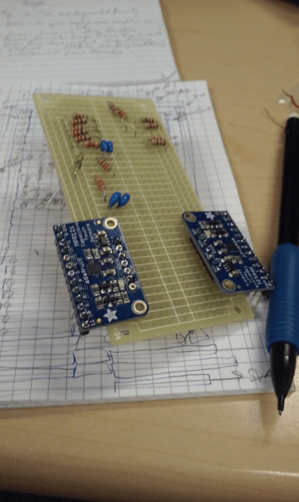
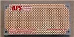
Figure 2: The unwired protoboard showing components.
Protoboard
The protoboard will hold all of the components which stand between the inputs/outputs and the Arduino 101. This includes the MPR121 Capacitive Touch Sensors, the mode switch, the IR sensor, and the output filters.
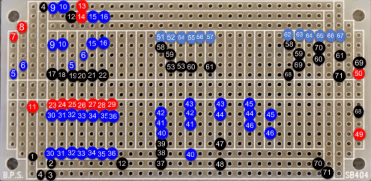
Figure 3: Labeled protoboard. See Legend in Table 1 below.
If you decided to use the proto-board that I used, the long, outer columns will serve as our power strips while the topmost and bottommost rows will connect to the Arduino. The volume slider, LED, mode switch, and speaker out will come from various nodes in the middle of the strip board so pay close attention to the picture above. Otherwise, you are of course free to build off the schematic however you wish.
The black dots are normal insulated wire, red dots are breadboard wires (with the header pin side attached to the Arduino 101 and the other side stripped and soldered to the protoboard. The dark blue dots are the leads of components and the light blue dots are the short header on the MPR121 breakout board.
If two dots share the same number, this means that these dots represent the end points of the same wire or component, while dots without a partner attach to some external component. Start by soldering all of the components (blue) to the board, then continue reading, referring back to this diagram for wire connections.
Table 1: Legend for protoboard landing wires.
For the MPR121 breakout boards I wired the SCL, SDA, GND, and VIN headers to their respective partners on the other breakout board before connecting that header to the outer rows of the proto-board (from there they will be wired to the Arduino.) Take care in wiring the headers to each other. I connected the ADDR pin on the second board to the SDA pin because of how the breakout board assigns I2C addresses. A small, bare jumper connects the two on the bottom side of the board.
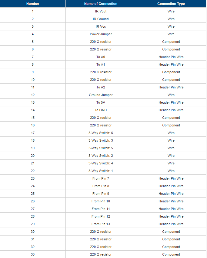
Figure 4: The output filter components, with main output wires (brown is the signal, white is the ground). These go to the 1/4" jack.
Enclosure
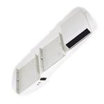
Our input and output devices (from the keys to the speaker outs) have to be mounted onto the enclosure before we can wire them up to the protoboard. I have chosen this Hammond enclosure because of it is made of ABS plastic and is the perfect length for a portable keyboard.
I used a Dremel tool and power drill extensively to cut holes in my enclosure. If you do not have access to these tools, you can make your enclosure out of something thinner, like cardboard. Once you have your circuit built, feel free to throw it in any kind of box that you like. For this reason, I will not provide schematics for the enclosure.
Attach Inputs and Outputs to Enclosure
Figure 5: Enclosure lid with peripherals' holes drilled.
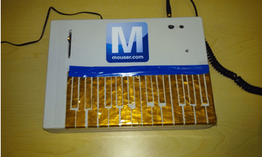
The keys are standard piano key shapes, carefully cut out of thin copper sheets. I used epoxy to glue the keys in place. When placing the keys on your enclosure, make sure to place them carefully; no keys should touch, and each needs to be straight. Once the keys are placed, we need to use a very small drill bit to drill a hole through the top of each key and through the enclosure.
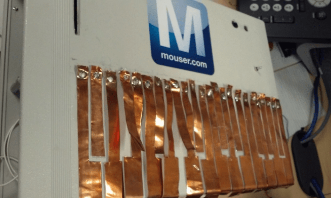
Figure 6: Loose keys after soldering
To attach the 3-way switch, I drilled a hole the size of the toggle (but smaller than the actual red base) and hot glued the switch in place from the bottom of the enclosure.
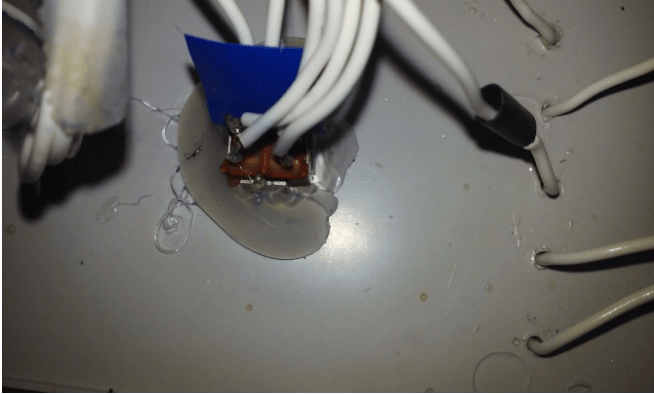
Figure 7: Mode switch wired and glued.
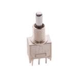
The volume pot on my enclosure is similarly glued to the underside of the plastic, with the slider sticking out through a thin rectangular hole I chiseled out with the Dremel tool. You can just as easily stick the potentiometer on top of the enclosure and drill holes for the wires to slide through.
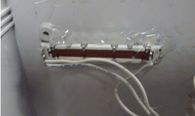
Figure 8: Volume Slider glued and wired up.
The IR sensor has two holes on the sides to accommodate drilling to the enclosure. I took a different route by drilling and carving two holes into the top of the box before gluing the IR sensor to the bottom side. This makes the enclosure look more seamless but is not necessary.
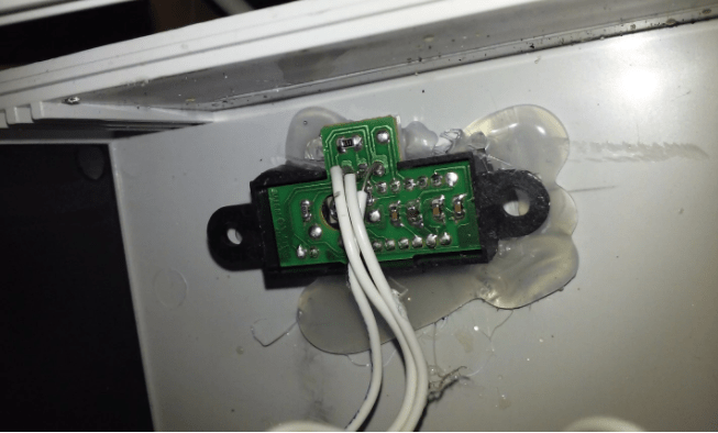
Figure 9: IR sensor glued and wired.
You will need to drill at least two more holes: The output jack needs a hole where the signal will go out to an amp, while the power adapter needs a hole to plug into the Arduino. I also drilled and carved an opening for the USB port on the Arduino in case I need to connect it to a computer for debugging.
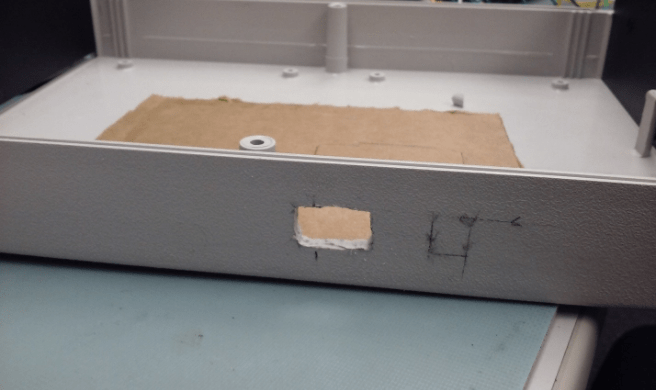
Figure 10: The USB port hole and a marking for the power port.
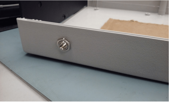
Figure 11: The output jack.
Wire I/O to protoboard
Once we have the inputs and outputs attached to our enclosure, we can start wiring them up to the protoboard. All of the user interface elements are attached to the enclosure and will be wired to the protoboard in some way.
First, the keys. For each key, solder a wire to one of the numbered holes in the Adafruit breakout board. Strip about a centimeter off the other end and feed it from the bottom of the enclosure through the hole so that it touches the corresponding key. Then solder the wire to the copper key. Be careful, the copper gets hot quickly. Repeat for all 24 keys.
Next, we need to wire the volume potentiometer. There are six pins on our Bourns slide potentiometer, but we only need three of them. Looking at the bottom of the slide pot with the 4-pin side to the left, the bottom pin is the “2,” meaning that it is the output of the potentiometer. This should be wired to the protoboard right before the high-pass filter. The pin above it is the “1,” the input, which, as you can see from the schematic, is wired to the output of the summer. Our summer’s output is soldered to the rail running parallel to the power rails. The bottom pin on the right side (with the two pins) is the ground pin. Wire that to the ground rail.
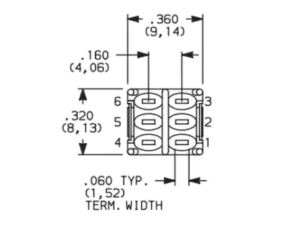
Figure 12: 3-way switch pin numbering.
The 3-way switch has six pins on the bottom of it, so this step can get confusing. Each of the pins has a number designated to it, though they are not printed on the switch, so you will need to refer to Figure 12 or the datasheet (specifically page F-38) to understand where to wire the ends of the switch. Our switch is the second table of the datasheet. The pins are labelled 1-6, with 1-3 on one side and 4-6 on the other. Once you identify the pins from the datasheet, you can solder wires from the pins to their corresponding places on the protoboard (See Table 1).
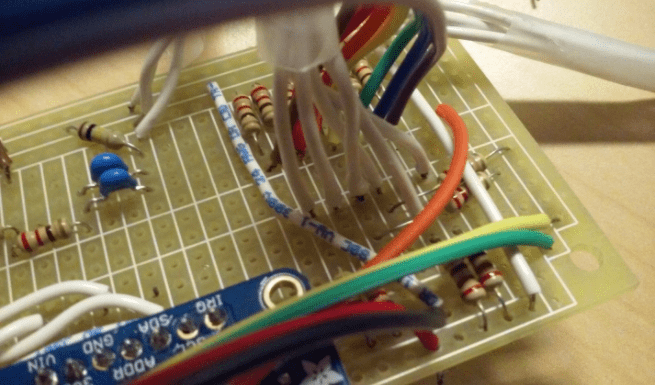
Figure 13: The digital pins (in rainbow) and the 3-way switch (in white).
The IR sensor is fairly straightforward. Three wires will connect the pins on the back of the IR sensor to its region on the protoboard. When soldering wires to the pins on the back of the IR sensor, be VERY careful not to solder two pins together. Look at the datasheet to learn which pin is which. The middle pin is ground, so solder that wire to your ground strip on the protoboard. Similarly, the Vcc pin will be connected to your 5V strip. The last pin, Vo, is your data wire. This should be soldered to the designated place on the protoboard.
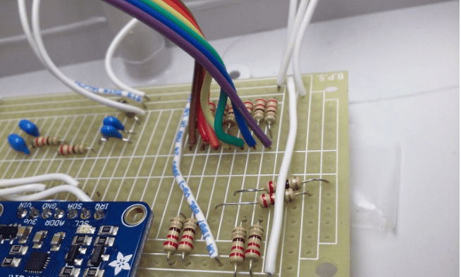
Figure 14: The volume slider wires (on left) and the IR sensor wires (on right).
The ¼” jack has two tabs with small holes in them. One of these pins (the sleeve, or the shorter one) should be wired to ground. The other one (the tip, or the longer one, needs to connect to the output row on the protoboard.
The MPR121 boards need to be powered and grounded as well as connected to the I2C pins of the Arduino. I used jumper wires to connect the 5V, GND, SCL, and SDA pins of one MPR121 to the corresponding pins of the other board to “tie” the boards together. Then I wired the pins of the second board to their ultimate destinations (5V and GND to the protoboard power strip, SCL and SDA to the Arduino).
Connect Protoboard to Arduino
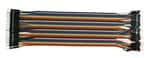
The Arduino has 7 note pin outputs (digital pins 7, 8, 9, 10, 11, 12, and 13) which are summed on the protoboard. You can use breadboard cables with male ends to plug into the Arduino header and solder the other ends to the protoboard. The Arduino will also supply 5V and a ground (GND) reference to the protoboard using breadboard cables as well.
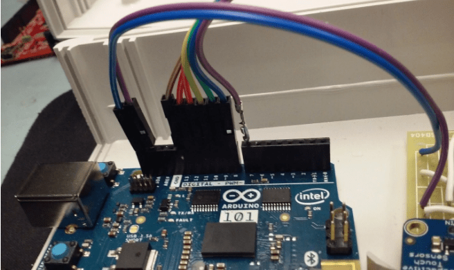
Figure 15: Digital Pin outs (7-13) and I2C jumpers (SDA in purple, SCL in blue).
The protoboard routes the I2C data from the MPR121s to the Arduino while routing the power and ground from the Arduino to both MPR121s. This is why we brought the SDA and SCL nodes from both boards together and soldered them to the protoboard. Soldering a breadboard cable to these nodes and plugging the male pin ends to the respective SDA and SCL header slots will allow the breakout board to communicate information about the keys to the Arduino.
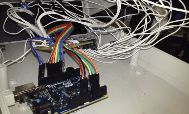
Figure 16: A fully wired synthesizer. The rest of the header wires (the power, ground, and analog ins) can be seen in the foreground.
The 3-way mode switch will be directing voltage into two of the Arduino’s analog pins. The top two rows on the right side of the board (the side of the breakout boards, where the boards take up most of the bottom) will be wired to analog pins A0 and A1.
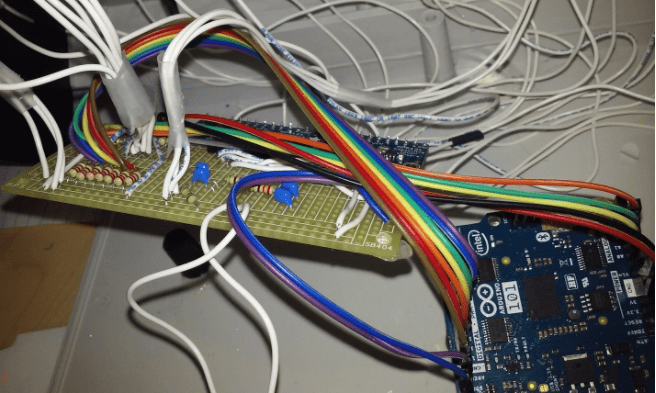
Figure 17: The wired protoboard and Arduino.
Once you have the Arduino connected to the right places on the protoboard, the peripherals all soldered to the protoboard, and the keys all attached and not touching, you can load the code onto your Arduino 101 (if you haven’t already), connect the Arduino to power, and plug your synthesizer into an amplifier or a pair of headphones with a 1/8” to ¼” adapter.
OPTIONAL: If you would like some indication that the synthesizer is on and working, you can wire up the LED on the volume slider. Simply solder a 220Ω resistor to a free space on our solder board and wire the slide pot like you would a normal LED.
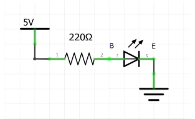
Figure 18: Schematic of slide pot LED.
Connect one end of the resistor to the 5V power strip on the protoboard and connect the other end to the “B” pin of the slide pot. The B pin is on the side of the pot with 2 pins, on the outside. The “E” pin is the only remaining pin on the opposite side of the side pot. This one should be connected to ground.
Credits
Related products


Leave your feedback...