
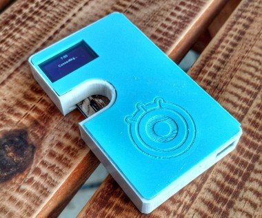
Iot Wallet (smart Wallet With Firebeetle Esp32) By Igor

Made by DoYouKnowArduino
About the project
There are several ways to use this tutorial. You can use it to:- Learn how to track and update your asset values for a particular currency using a Google spreadsheet;- Program an ESP32 using the Arduino IDE;- Read values from a Google spreadsheet using an ESP32 device;You can use part of this tutorial to create your own gadgets.
Items used in this project
Hardware components


View all
Story
Step 1: Tools and Materials

For this project, the following tools were used:
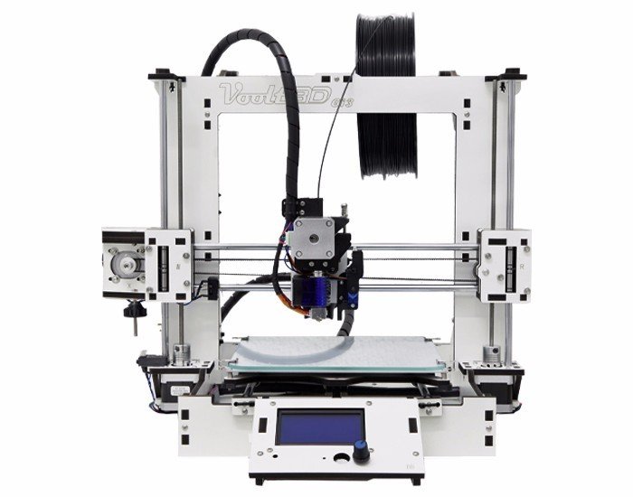
- 3D printer. I used it to print my wallet (with flexible filament) and produce a case for the electronics (with regular PLA filament). You can find some inexpesive 3D printers online that will work just fine for this project (link).
- 1.75mm PLA filament (link / link / link). I used rigid black PLA filament for printing the case where the electronics are encased and protected. This way they won't get crushed if I sit with on my wallet, or if it accidenty falls on the floor.
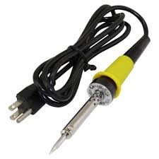
- Solder iron and wire. I needed it to solder some wires between the electronic components, as you'll se later.
- Super glue. The 3D design was printed in different parts. I used some super glue to stick them together.
I used the following hardware parts for my project:
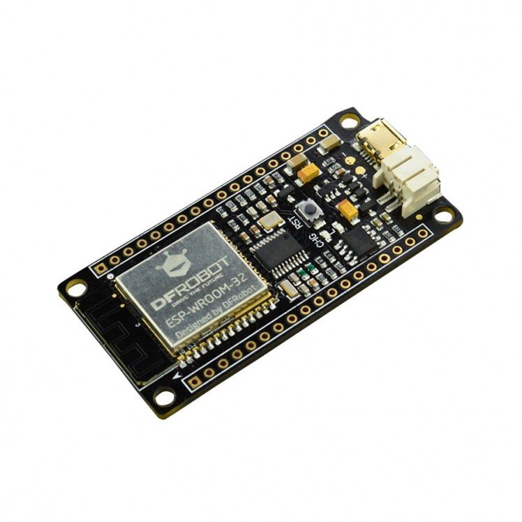
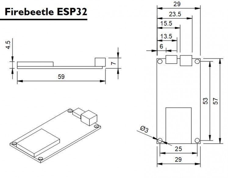
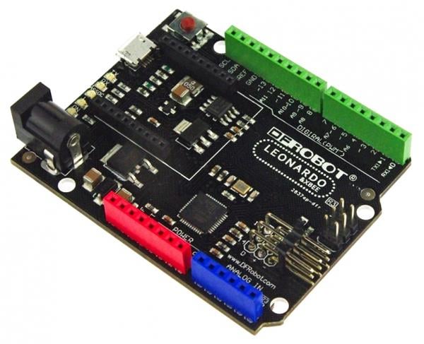
- Firebeetle ESP32 dev board (link). Firebeetle ESP32 board is really easy to use and program using Arduino IDE. It has built-in Bluetooth and Wi-Fi modules, so you can use it in a variaty of projects. It has a connector for a 3.7V battery, which was really usefull for assembling this project. I has also a built-in battery charger. It will recharge the battery when connected to an USB plug. You can also use other ESP32 based boards (link / link), or ESP8266 ones (link / link / link) if you wish. Deppending on the board you choose, it would be a little more difficult to connect and recharge the battery. The dimensions of the case will also need to be verified.
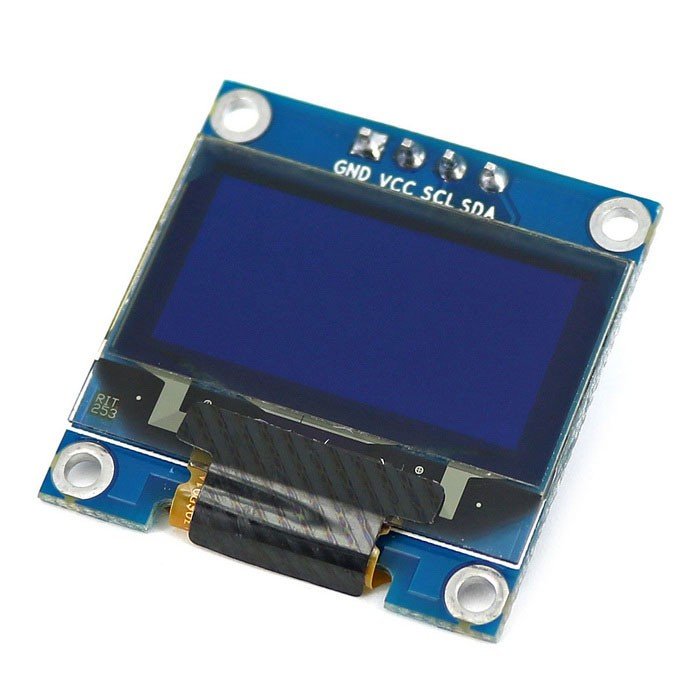
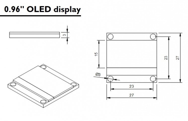
- OLED display (link / link). It was connected to the ESP board, for displaying the values obtained from Google Spreadsheet.
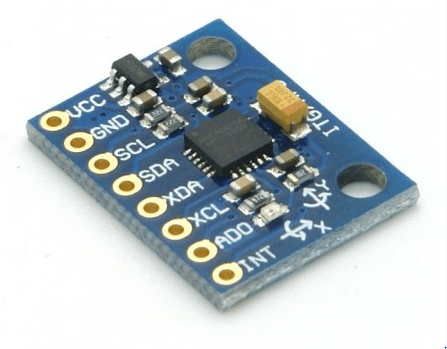
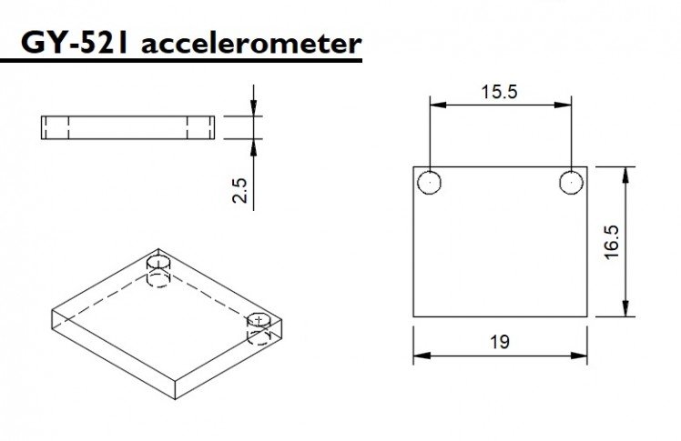
- GY-521 accelerometer (link / link). It was used as a step counter.
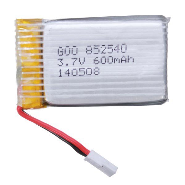
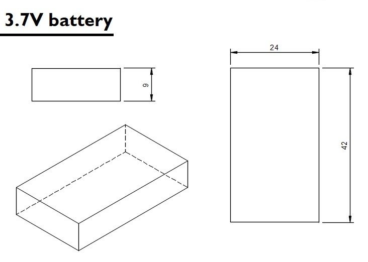
- 3.7V battery (link / link). I used to power the whole circuit.
- Wires.
- Micro USB cable.
- M2x6mm bolts (x9)
- M2x1.5mm nuts (x5)
The links above are only a suggestion of where you can find the items used in this tutorial (and maybe support my future tutorials). Feel free to search for them elsewhere and buy at your favorite local or online store.
As it was said before, some ESP dev boards won't have a built-in battery connector (and charger). In that case, you'll need an external battery charging module (a TP4056 (link / link), for instance). It will possibly require a mini USB cable for the connection between the charger and an USB port.Did you know you can buy a Anet A8 for only $155.99? Get yours at Gearbest: http://bit.ly/2kqVOdO
Step 2: 3D Modeling

In this step I present how the wallet was designed for 3D printing using flexible filaments. I also introduce the step-by-step involved in design of the case where electronic components are protected.
If you're only interested in printing your own wallet, skip to the next step, where you can find finished stl files. If you are not interested in 3D printing, skip a few more steps. If you are interested in 3D printing, but do not have a printer, why not buy one? Did you know that it is possible to buy a 3D printer for only 359.99 USD? Click HERE!
The wallet was designed to hold three cards and some electronics (microcontroller, display, and battery). An elastic might be used for holding additional doccuments and maybe some paper money. It was desgined using Fusion 360 CAD software.
The model is composed of only two different part: cap, body. I'll detail how I drawed each of this parts, in case you want to replicate it on your own design.
1. Components
First I made a simple representation of each component used on my wallet. They don't have to be very detailed, but should have the right measurements. This was important to help define the relative position of each component inside the wallet. This way, I had to create a model for the ESP32 Firebeetle, OLED display, battery, and of a standard credit card.
2. Arrange the components
With a model of each component, you can play with their position and choose the best position for each one. I wanted to create a gadget as slim and as small as possible. This way, I tried to organize the devices to use a footprint close to a standard credit card area.
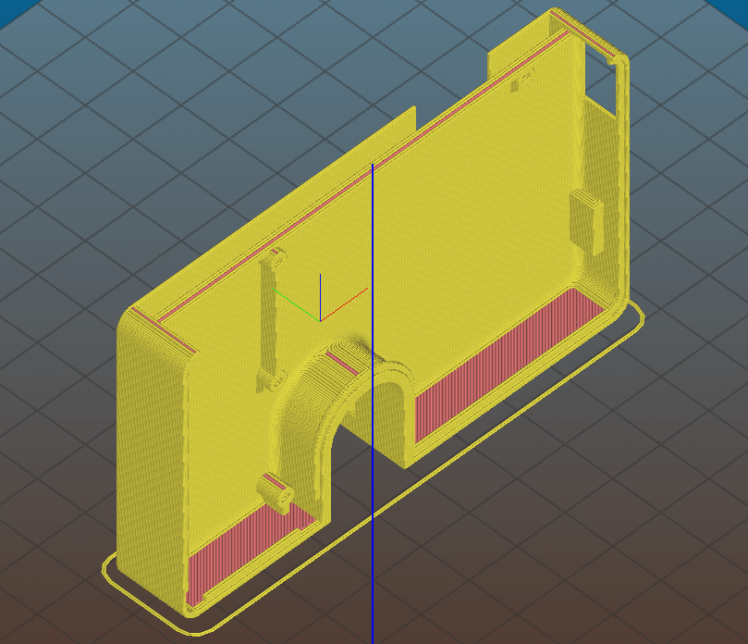
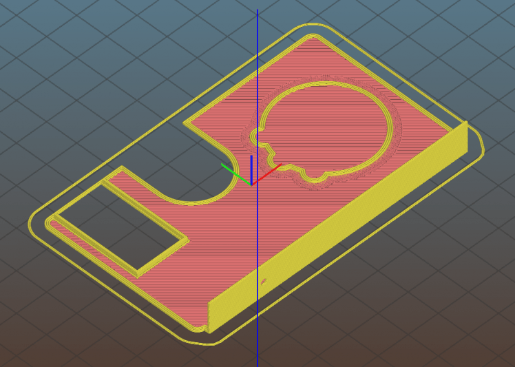
3. Drawing the sketches
After choosing the location of the instruments, the sketches were drawn and the structure was extruded.
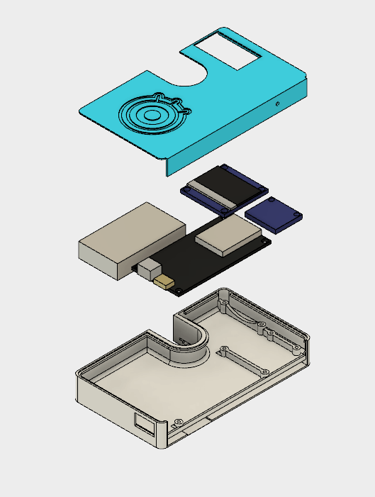
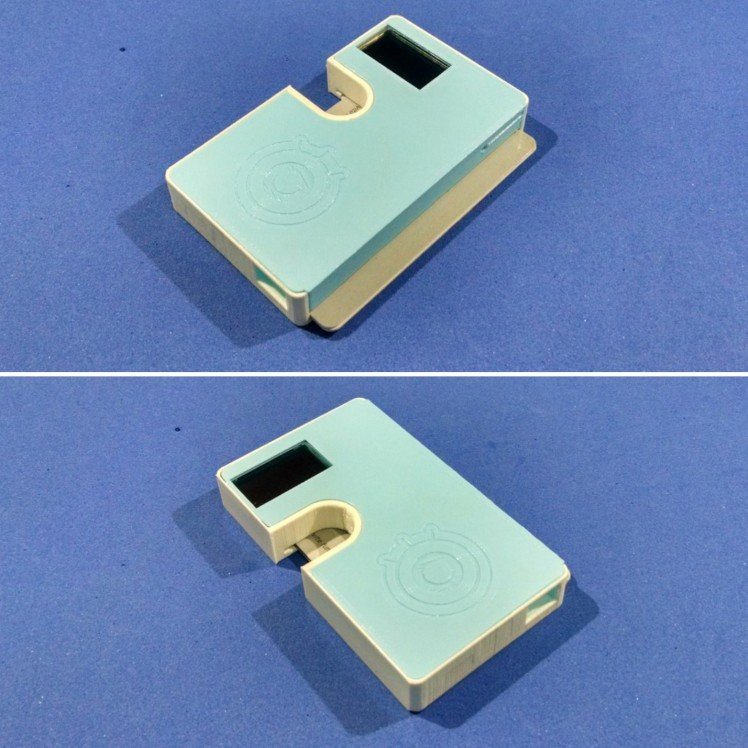
The model was divided in two parts: the body of the wallet and the front cover. The body has holes for the bolts for the installation of the electronics. It also has hole that allows connecting an USB cable to the microcontroller (for uploading a code or charging the battery). It was were designed usin 0,8 mm walls, and have space for 3 cards. The front conver is glued to the wallet, protecting the electronics. It also has a hole for the touch button.
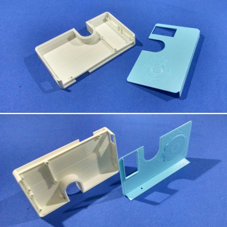
Step 3: 3D Printing

You can download all the stl files on the following websites:
https://www.thingiverse.com/thing:2886806
The whole print took me around 2h30, printed with 0.2 mm resolution and 10% infill.
This is a experimental prototype. Notice that it was designed for a given ESP32 dev board model (the ESP32 Firebbetle). If you want to use a different model, please send a comment and I can see if it's possible to change model dimensions to fit your needs.
If you don't have a 3D printer, here are some things you can do:
- Ask a friend to print it for you;
- Find a hacker/maker space nearby. The parts used in this model can be printed quickly (around 3 hours). Some hacker/maker spaces will only charge your for the materials used;
- Buy your own 3D printer. You can find the Creality3D CR10 for only $359.99. Use the coupon code cr10mini3d at Gearbest and get yours: http://bit.ly/2JIUVrf
- Improvise! You can try to assemble a structure without 3D printed parts.
Interested in purchasing a DIY Kit? If enough people are interested, I might be offering a DIY kits on Tindie.com. If you would like one, send me a message.
Step 4: Wiring Up the Circuits
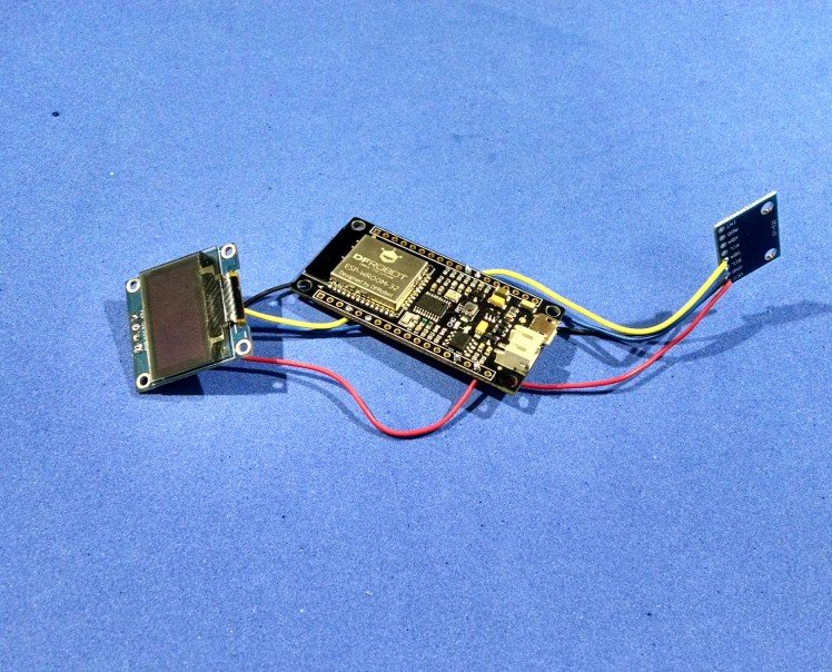
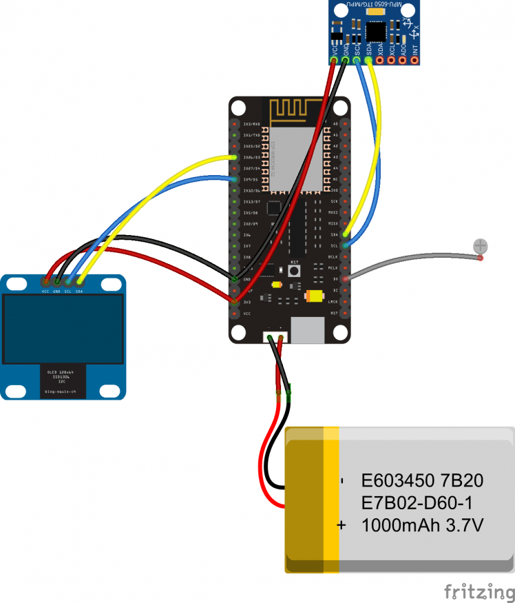
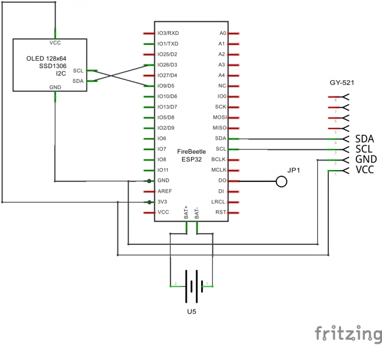
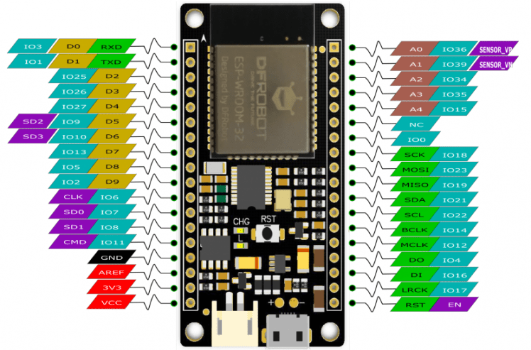
The circuit uses four main components:
- Firebeetle ESP32. This development board already comes with WiFi module, and a connector for a 3.7V battery. It can also charge the battery if you connect USB cable is connected.
I soldered the wires before putting the electronics inside the case. The components were connected as shown in the schematics.
OLED display:
- Display Vcc pin -> ESP32 3V3 pin
- Display Gnd pin -> ESP32 Gnd pin
- Display SDA pin -> ESP32 D3 pin
- Display SCL pin -> ESP32 D5 pin
GY-521 (accelerometer):
- GY-521 Vcc pin -> ESP32 3V3 pin
- GY-521 Gnd pin -> ESP32 Gnd pin
- GY-521 SDA pin -> ESP32 SDA pin
- GY-521 SCL pin -> ESP32 SCL pin
The accelerometer isn't mandatory. You might even remove it to save some battery, if you wish.
Step 5: Assembling the Components
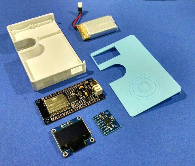
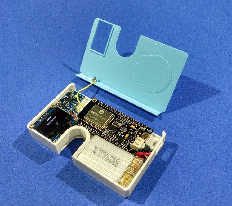
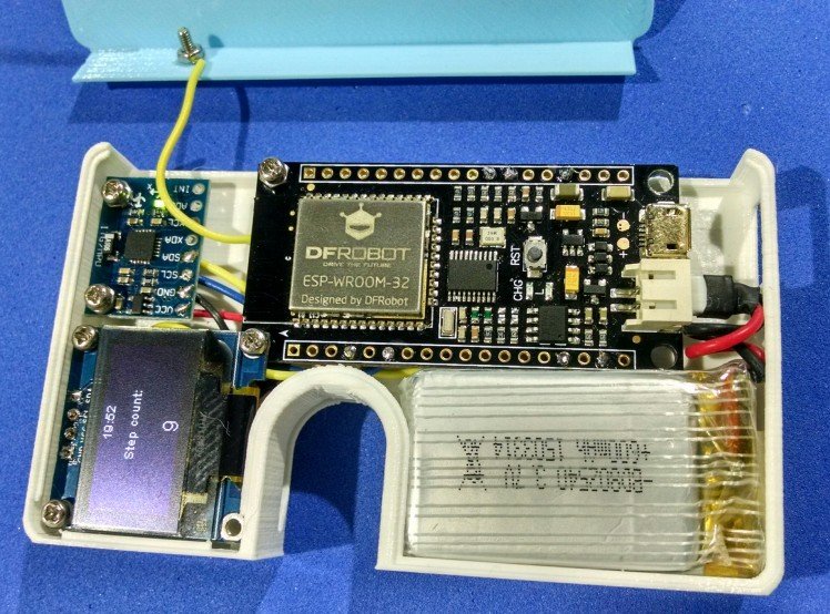
After printing the case and soldering the componentes, it's possible to assemble the gadget. I used M2 bolts and nuts to attach the electronics to the structure. The components shall be installed in the following order:
- Battery
- Display
- Accelerometer
- ESP32
- Button
The battery had to be connected to ESP32's power connetor before attaching the ESP32 to the case using M2 bolts and nuts. Due to space limitations, there is an interference between the case and the connectors, and you won't be able to plug/unplug the battery once the microcontroller is fixed.
The button is made of a bolt + nut connected to a wire. That wire is soldered to a touch pin of the ESP32.
You can glue the front cover to the body of the wallet using a super glue. It's recommended to that only after uploading the code and testing the gadget, as it's described later.
Step 6: Working With Google Spreadsheet

A first step to improve the organization of your financial life is to start to record your income, investments and expenses. The use of Google spreadsheet would be a good and free tool for that, specially if you're dealing with the stock markets or cryptocurrencies.
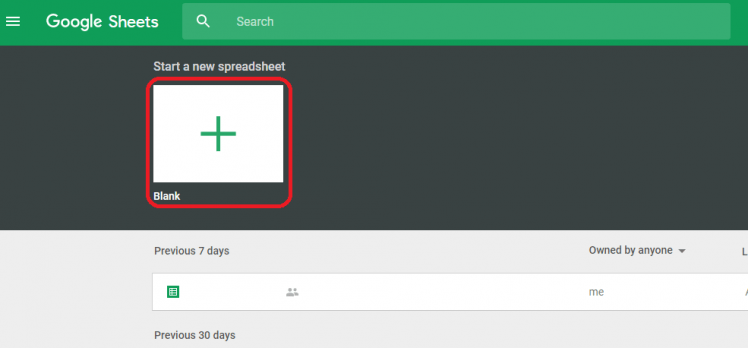
The use of Google Spreadsheet would also allow you to create a >https://docs.google.com/spreadsheets/u/0/ and add a new blank spreadsheet.
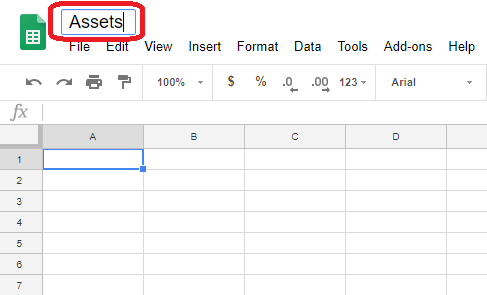
2. You can rename your Spreadsheet by clicking its title on top left corner. Since I want to track my different assents (cryptocurrencies, stocks, etc.) I named it 'Assets'.
3. Install Cryptofinance Add-on. It will be used for getting the value of various cyptocurrencies.
a. Go to add-ons on the menu, and click "Get add-ons";
b. Search for "cryptofinance" and click "+FREE" to install it;
4. I used first column to store the names of my assets. Use the market cap for cryptocurrencies or stocks. For instance, BTC for Bitcoin, ETH for Etherium, GOGL34 for Google stocks, etc. The first cell is reserved for the title of column ('Assets').
5. Second column stores the amount of that asset. For instance, if you have 0.1 Bitcoin, enter that value on the line equivalent to BTC. As before, the title of the column ('Amount') was fulfilled in the first line.
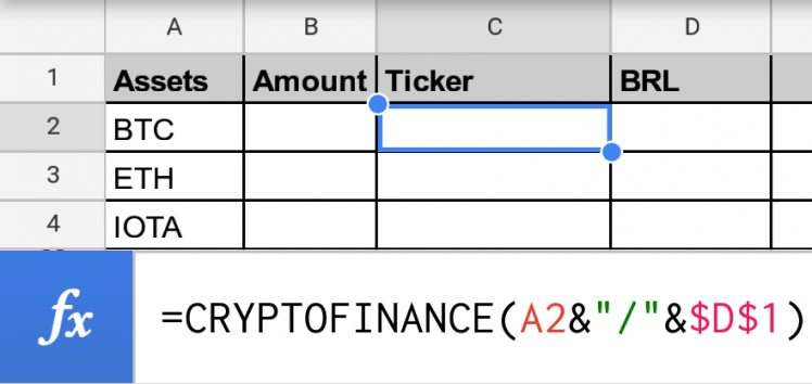
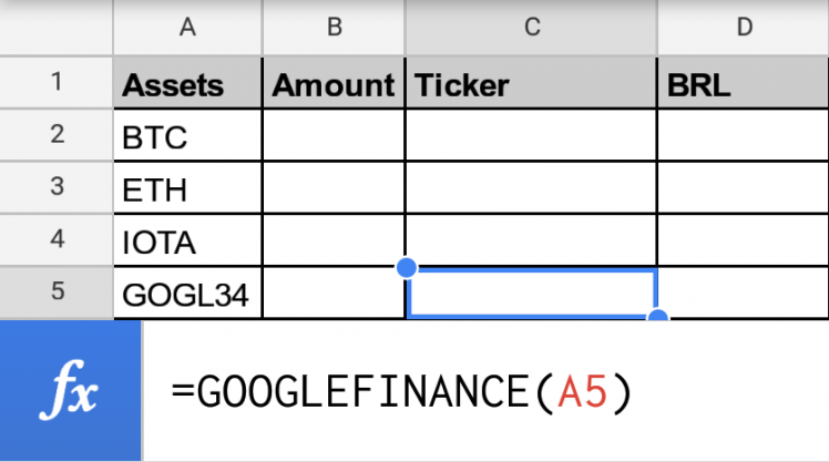
6. Third column will store the ticker for each asset, i.e., their conversion to a given currency. Those values will be loaded from the internet using specific functions (CRYPTOFINANCE for cryptocurrencies, and GOOGLEFINANCE for regular stock market).
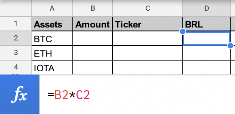
7. Fourth column stores the value of the asset, converted to the currency you chosed.
Step 7: Share Google Spreadsheet
This part of my project was based on José Morais amazing tutorial. You can find more at: https://portal.vidadesilicio.com.br/lendo-dados-do-google-planilhas-banco-de-dados/
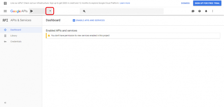
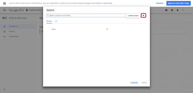
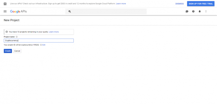
- Go to https://console.developers.google.com/apis and create a new project. I named it 'Cryptocurrency';
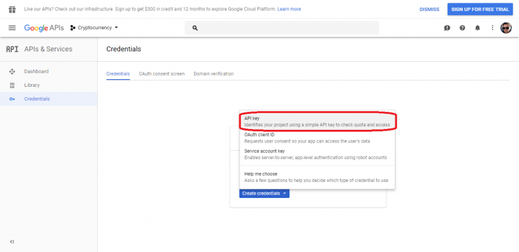
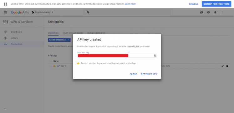
- Under 'Credentials' select 'Create credentials'. Copy that value somewhere (you'll need it on your code);
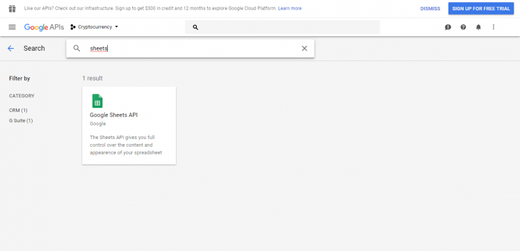
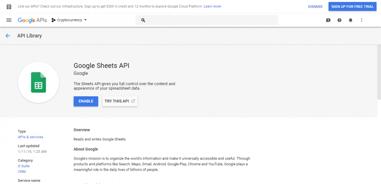
- Go back to https://console.developers.google.com/apis. Click on 'Library', select 'Google sheets API', and 'Enable' it;
- Open the spreadsheet you want to use as a rel="nofollow">https://www.arduino.cc/en/main/software
Download it for free, install it on your computer and launch it.
2. Adding ESP32 board
Arduino IDE already comes with support to a lot of different boards: Arduino Nano, Mine, Uno, Mega, Yún, etc. Unfortunatly ESP32 isn't by default among those suported development boards. So in order to upload your codes to a ESP32 base board, you'll have to add its properties to Arduino's software first.
- Navigate to File > Preferences (Ctrl + , on Windows OS);
- Add the following URL to Additional Boards Manager textbox (the one on the bottom of the Preferences window):
https://git.oschina.net/dfrobot/FireBeetle-ESP32/raw/master/package_esp32_index.json
- If the text box wasn't blank, it means had already add other boards before on Arduino IDE before. Add a comma at the end of the previous URL and the one above.
- Hit "Ok" button and close the Preferences Window.
- Navigate for Tools > Board > Boards Manager for adding your ESP32 board.
- Type "FireBeetle-ESP32" on the search text box, select "FireBeetle-ESP32 Mainboard by DFRobot DFRDuino" and install it.
Now your Arduino IDE will be ready to work with ESP32 FireBeetle board.
If you wish to use an ESP8266 based board, add the appropriate board.
3. Adding the libraries
The following libraries will be used for our Arduino code. Download the following libraries:
- Arduino http client library (https://github.com/arduino-libraries/ArduinoHttpClient)
- esp_deep_sleep.h library (https://github.com/pycom/esp-idf-2.0/blob/master/components/esp32/include/esp_deep_sleep.h)
- WiFiClientSecure library (https://github.com/espressif/arduino-esp32/tree/master/libraries/WiFiClientSecure)
- ArduinoHttpClient (https://github.com/arduino-libraries/ArduinoHttpClient)
- ArduinoJson library (https://github.com/bblanchon/ArduinoJson)
- SH1106 library (https://github.com/wonho-maker/Adafruit_SH1106)
Navigate to Sketch-> Include Library -> Manage Libraries... on your Arduino IDE and add the libraries above.
............
Now that your dev environment is ready, let's move on to the next step!
Step 9: Arduino (ESP32) Code


At this point the gadget is almost finished!
Download the Arduino code and open it on the Arduino IDE. Some parameters will have to be updated (WiFi router SSID and password, Google spreadsheet ID and password, etc.). Update them, and upload the code to the ESP32. The code will start running immediately.
The ESP32 will enter deep sleep mode. Whenever touch button is pressed, the microcontroller will wake up, connect the WiFi network and read the >https://www.instructables.com/id/Minimalist-IoT-Cl...
Download the Arduino code and open it on the Arduino IDE. Update the parameters (WiFi router SSID and password, Google spreadsheet ID and password, etc.), and upload the code to the ESP32.
Now your IoT wallet will periodically pool current time from Google server and display it on the OLED display. Notice this will consume more battery, once the ESP will wake up regularly to check the time and update the display. The display will also consume some milliamps for displaying the clock all the time.
Step 12: Bonus Round #3: Improve Your Fitness, Improve Your Finances!


The best long-term investment you can make is to take care of your health. A healthy life can lead to fewer expenses with medicines, health insurance and miracle diets, which can lead to a happier and more economically stable life.
In this step I show you how to turn your smart wallet into a step counter, capable of recording your physical activity. This can motivate you to reach greater distances and save a few cents on each step. Registered >link).
Create Thingspeak Channel
- Sign in at https://thingspeak.com/
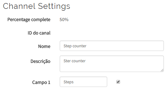
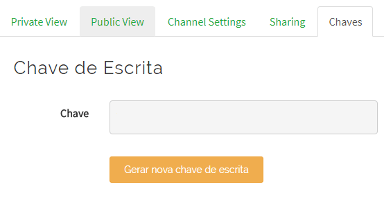
- Click Channels > New chanell add create a channel named "Step counter". It will create a >https://www.instructables.com/id/IoT-Air-Freshner-...
https://www.instructables.com/id/Minimalist-IoT-Cl...
https://www.instructables.com/id/3D-Printed-Articu...
https://www.instructables.com/id/Nunchuk-Controlle...
https://www.instructables.com/id/3D-Printed-Tool-H...
Liked any of my projects? Please consider supporting my future projects with a small Bitcoin donation! :D
BTC Deposit Address: 1FiWFYSjRaL7sLdr5wr6h86QkMA6pQxkXJ
Credits
DoYouKnowArduino
Offering quality microcontroller, shield, sensors, electronic components, iot gateway/node and robot kit with arduino, lattepanda, raspberry pi and intel edison/cuire/joule.
Related products


Leave your feedback...