

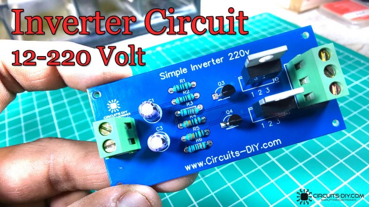
Inverter Circuit Using Irfz44 Mosfets

Made by CircuitsDIY
About the project
In this tutorial, we are going to make a simple and easy inverter circuit using IRFZ44 Mosfets
Project info
Difficulty: Easy
Estimated time: 1 hour
License: GNU General Public License, version 3 or later (GPL3+)
Story
Details
An inverter is a simple electronic device that can be used to provide backup power in case of a blackout or grid failure. An easy-to-build inverter can simply do this by supplementing power from a DC battery and translating it into a stable AC signal of the desire voltage level.
Inverters have found their application in every industry, from serving as power backups at home to function as key auxiliary power units for complex networking equipment in NOC centers. In today's article, we are going to go over a step-by-step procedure on how to design an Easy Inverter Circuit using the 2SC1815 NPN transistors.
JLCPCB is the foremost PCB prototype & manufacturing company in china, providing us with the best service we have ever experienced regarding (Quality, Price Service & Time). We strongly recommend ordering PCBs from JLCPCB, all you need to do is just download the Gerber file and upload it to the JLCPCB website after creating an account as mention in the video above, visit their website to look for more!.
Hardware RequiredYou will need the following parts to build this project:
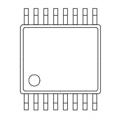
2SC1815 Pinout
Circuit DiagramThe working of this inverter circuit is as follows. Here, we are using two 2SC1815 transistors, configured as a multivibrator circuit running in astable mode, in order to generate a free-running square wave. On powering On the circuit using a 12V DC Battery, a square wave signal is generated by the multivibrator circuit, but, in order to run an AC device without any issues, we require a pure AC sine wave signal from the inverter. This is achieved by chopping off the excess RMS voltage of the astable square wave signal from the multivibrator circuit.
Credits
Related products


Leave your feedback...