
How To Use Adc On Raspberry Pi Pico Using Micropython

Made by rau7han
About the project
In this guide we will show you how to use the ADC on your Raspberry Pi Pico using MicroPython. We will also go over some of the basic concpt
Project info
Items used in this project
Hardware components

Story
In this tutorial let’s know aboutRaspberry Pi Pico ADC, How it works, what are its uses, Pinout, and finally how to read the ADC value of it with a MicroPython example code.
In this tutorial, we will use the Pico board to perform an ADC conversion. The Raspberry Pi Pico has four 12-bit ADC channels, but one of them is connected to the internal temperature sensor. The remaining ADC is found at GPIO26, GPIO27, and GPIO28 as ADC0, ADC1, and ADC2, respectively. Read also. Raspberry Pi Pico Getting Started Tutorial.
Hardware Required to Complete ADC on Raspberry Pi PicoWe need the following parts to complete the ADC on the Raspberry Pi Pico.
- Raspberry Pi Pico
- Potentiometer (10K ohms)
- 0.96" Inch I2C 128x64 OLED Display Module 4 Pin
- Connecting Wires
- breadboard
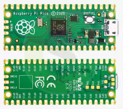
Raspberry Pi Pico. is a microcontroller board based on a custom-designed chip (RP2040) by Raspberry Pi in the UK. RP2040, the chip at the heart of Pico, is an ultra-powerful Dual Core ARM Cortex-M0+ clocked at 133MHz with 256KB RAM, and2MB of on-board QSPI Flash memory for code and data storage.
It also has 30 GPIO pins and lots of interfacing options including 2 × SPI, 2 × I2C, 2 × UART, 3 × 12-bit ADC, and16 × controllable PWM channels.
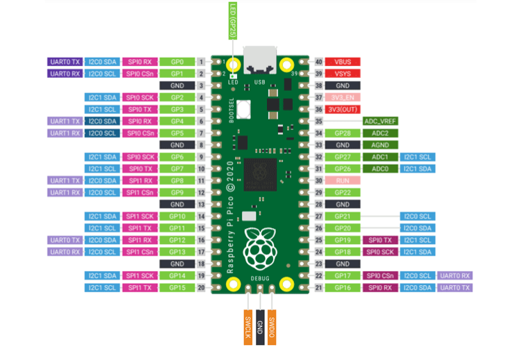
Moreover, 26 of the GPIO pins are multi-function, which means we can configure those pins to a different behaviour like UART/I2C/SPI/GPIO as given in the image below:
Raspberry Pi Pico PinoutRaspberry Pi Pico has a total of 40 input and output pins out of which 26 are multipurpose GPIOs working at 3.3V and 8 ground pins.
Apart from these pins, it also has 3 pins for debugging. The below image taken from the official datasheet of Raspberry Pi Pico shows the layout of all the pins.
General Input and Output (GPIO) Pins on Pico:
The Raspberry Pi only uses 26 out of 30 GPIOs the RP2040 has to offer, 26 pins are exposed and an additional 27th pins can only be used for the onboard LED. The Raspberry Pi Pico’s GPIO is powered from the onboard 3.3V rail and is therefore fixed at 3.3V. GPIO0 to GPIO22 are digital only and GPIO 26-28 are able to be used either as digital GPIO or as an ADC input which can be done through software.
The communication options this board has to offer are:
- 2 × SPI
- 2 × I2C
- 2 × UART
- 3 × 12-bit ADC
- 16 × controllable PWM channels
- RP2040 microcontroller chip designed by Raspberry Pi
- Dual-core Arm Cortex M0+ processor, the flexible clock running up to 133 MHz
- 264KB of SRAM, and 2MB of onboard Flash memory
- The castellated module allows soldering directly to carrier boards
- USB 1.1 with device and host support
- Low-power sleep and dormant modes
- Drag-and-drop programming using mass storage over USB
- 26 × multi-function GPIO pins
- 2 × SPI, 2 × I2C, 2 × UART, 3 × 12-bit ADC, 16 × controllable PWM channels
- Accurate clock and timer on-chip
- Onboard temperature sensor
- Accelerated floating-point libraries on-chip
- 8 × Programmable I/O (PIO) state machines for custom peripheral suppo
Most microcontrollers nowadays include built-in ADC converters. It is also possible to attach an external ADC converter to any type of microcontroller. ADC converters are usually 10 or 12 bits, including 1024 to 4096 quantization levels.
A 16 bits ADC has 65536 quantization levels. A Raspberry Pi Pico has 12 Bits ADC with a quantization level of 4096
Raspberry Pi Pico ADC Channels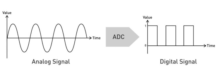
The Pico ADC channels on the Raspberry Pi allow for a wide range of applications. With eight channels, the Pico ADC can be used to measure a variety of different signals.
The most common use for the Pico ADC is measuring the voltage of a battery. However, the Pico ADC can also be used to measure current, temperature, and even humidity.
The Pico ADC has a resolution of 12 bits, which means that it can measure voltage with an accuracy of 0.025%. This is incredibly accurate, and it means that the Pico ADC is perfect for applications where precision is important.
The Pico ADC can also be used to measure a wide range of voltages, from 0-3.3V. The Pico ADC is a great choice for applications where precision is important. With its high accuracy and wide range of voltages, the Pico ADC is perfect for a wide range of applications.
The following table shows that the input signal for ADC0, ADC1 and ADC2 can be connected with GP26, GP27, and GP28 pins, respectively.
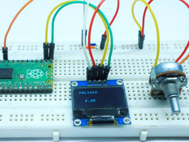
Raspberry Pi Pico ADC Connection DiagramThe below image displays the schematic for Raspberry Pi Pico with a potentiometer. Make your circuit as follows:
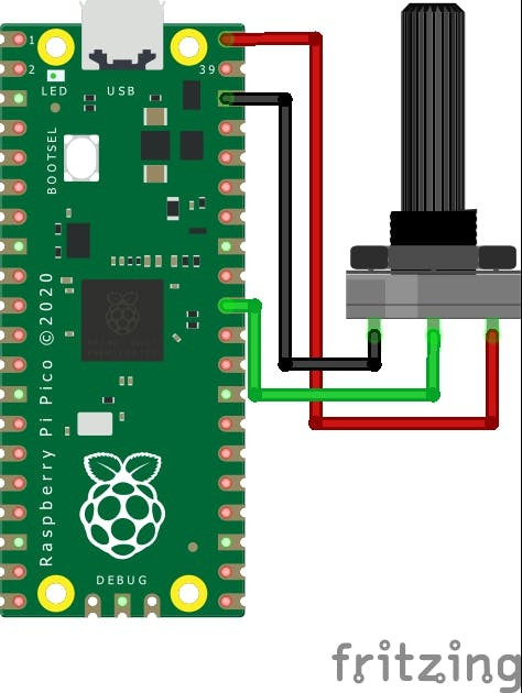
As we can see one terminal of the potentiometer is powered by 5v, the centre terminal is connected to an ADC pin, GP28 in our case and the last one is grounded (black).
Programming the Raspberry Pi Pico using MicroPython to Read ADC value on Shell.Following is the MicroPython script to read Analog input for Raspberry Pi Pico:
Now it’s time to write a code and check the Analog Reading. To do that you can use Thonny IDE. Copy the following code and hit the download & Run Button‘.
import machine
import utime
potentiometer = machine.ADC(26)
while True:
print(potentiometer.read_u16())
utime.sleep(2)
In this code part, I describe the ADC input connected at pin 26. Then to make an indefinite loop I make a while true. then I read the ADC value with the read u16 function on the shell monitor.
One important thing to note is the type of value we get back with the “read_u16” function is an unsigned 16-bit integer. This means it will vary between 0 and 65, 535, not 4095 as you might expect from a 12-bit ADC.
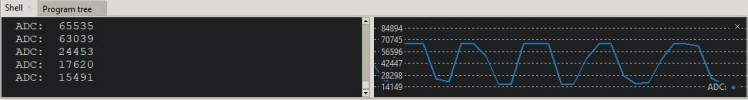
Run the script and observe the Shell, you should see the values there change as you move the potentiometer shaft. Here you can check more Example codes using raspberry pi pico ADC Example Code.
Similar Raspberry Pi Pico Projects- How To Use SSD1306 Oled Display With Raspberry Pi Pico
- RGB LED Using a Raspberry Pi Pico with MicroPython
- Joystick With Raspberry Pi Pico MicroPython Tutorial
- Flame Sensor With Raspberry Pi Pico Tutorial
- HC-SR04 Ultrasonic Distance Sensor With Raspberry Pi Pico Tutorial
- Raspberry Pi Pico Home Automation System
- Interface 16×2 Lcd Display With Raspberry Pi Pico
- Raspberry Pi Pico Weather Station Using Dht11 Sensor
- Interface Servo Motor With Raspberry Pi Pico
- Interfacing PIR Motion Sensor with Raspberry Pi Pico
Schematics, diagrams and documents
Code
Credits
Related products


Leave your feedback...