
How To Connect Mpu6050 To Esp32: Physical Setup And Code

Made by mahmood-m-shilleh
About the project
Learn how to easily get acceleration readings to start some cool projects with the ESP32 and MPU6050 Accelerometer.
Project info
Difficulty: Easy
Platforms: Espressif
Estimated time: 1 hour
License: GNU Lesser General Public License version 3 or later (LGPL3+)
Items used in this project

Story
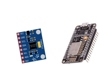
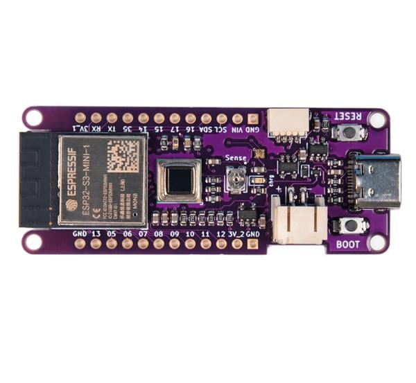
The ESP32 is a popular and versatile microcontroller and system-on-chip (SoC) that's widely used in various embedded systems and Internet of Things (IoT) projects. It was developed by Espressif Systems, a company based in China. The ESP32 is a successor to the ESP8266 and offers many improvements and additional features. In this tutorial, we show how to use the MPU6050 with this amazing microcontroller to start getting gyro and accelerometer values in real time, very easily with the Adafruit MPU6050 library in the Arduino IDE. All you will need is an ESP32 and a soldered MPU6050 which you can purchase here:
Also, be sure to subscribe and support the channel if you have not!
Subscribe:
Support:
https://www.buymeacoffee.com/mmshilleh
1-) Physical Connection
You can see the physical connection is super simple as the module uses I2C communication so we only need 4 jumper wires to get started here!
Step 2-) Add the Board and ConnectGo to the boards manager in Arduino and search esp32. Download the boards by Espressif. Then you can select the board in Arduino IDE followed by the port (after you plug into your computer). You should be good to go there.
Step 3-) Add Adafruit MPU6050 LibraryAdafruit has a convenient library that you can download straight from the Arduino IDE
Go to Library Manager, search MPU6050, and select the Adafruit MPU6050 library.
Step 4-) Run Example ScriptThey also have example scripts in their library now that you have it downloaded.
Go to File > Examples
In the section, you will see examples from external libraries, select the basic_readings example
You can upload this to your board right away if you have your connections ready and you should start seeing readings in the serial monitor. Make sure you open the serial monitor with the correct Baud Rate
The full code is here
// Basic demo for accelerometer readings from Adafruit MPU6050

#include <Adafruit_MPU6050.h>
#include <Adafruit_Sensor.h>
#include <Wire.h>

Adafruit_MPU6050 mpu;

void setup(void) {
  Serial.begin(115200);
  while (!Serial)
    delay(10); // will pause Zero, Leonardo, etc until serial console opens

  Serial.println("Adafruit MPU6050 test!");

  // Try to initialize!
  if (!mpu.begin()) {
    Serial.println("Failed to find MPU6050 chip");
    while (1) {
      delay(10);
    }
  }
  Serial.println("MPU6050 Found!");

  mpu.setAccelerometerRange(MPU6050_RANGE_8_G);
  Serial.print("Accelerometer range set to: ");
  switch (mpu.getAccelerometerRange()) {
  case MPU6050_RANGE_2_G:
    Serial.println("+-2G");
    break;
  case MPU6050_RANGE_4_G:
    Serial.println("+-4G");
    break;
  case MPU6050_RANGE_8_G:
    Serial.println("+-8G");
    break;
  case MPU6050_RANGE_16_G:
    Serial.println("+-16G");
    break;
  }
  mpu.setGyroRange(MPU6050_RANGE_500_DEG);
  Serial.print("Gyro range set to: ");
  switch (mpu.getGyroRange()) {
  case MPU6050_RANGE_250_DEG:
    Serial.println("+- 250 deg/s");
    break;
  case MPU6050_RANGE_500_DEG:
    Serial.println("+- 500 deg/s");
    break;
  case MPU6050_RANGE_1000_DEG:
    Serial.println("+- 1000 deg/s");
    break;
  case MPU6050_RANGE_2000_DEG:
    Serial.println("+- 2000 deg/s");
    break;
  }

  mpu.setFilterBandwidth(MPU6050_BAND_21_HZ);
  Serial.print("Filter bandwidth set to: ");
  switch (mpu.getFilterBandwidth()) {
  case MPU6050_BAND_260_HZ:
    Serial.println("260 Hz");
    break;
  case MPU6050_BAND_184_HZ:
    Serial.println("184 Hz");
    break;
  case MPU6050_BAND_94_HZ:
    Serial.println("94 Hz");
    break;
  case MPU6050_BAND_44_HZ:
    Serial.println("44 Hz");
    break;
  case MPU6050_BAND_21_HZ:
    Serial.println("21 Hz");
    break;
  case MPU6050_BAND_10_HZ:
    Serial.println("10 Hz");
    break;
  case MPU6050_BAND_5_HZ:
    Serial.println("5 Hz");
    break;
  }

  Serial.println("");
  delay(100);
}

void loop() {

  /* Get new sensor events with the readings */
  sensors_event_t a, g, temp;
  mpu.getEvent(&a, &g, &temp);

  /* Print out the values */
  Serial.print("Acceleration X: ");
  Serial.print(a.acceleration.x);
  Serial.print(", Y: ");
  Serial.print(a.acceleration.y);
  Serial.print(", Z: ");
  Serial.print(a.acceleration.z);
  Serial.println(" m/s^2");

  Serial.print("Rotation X: ");
  Serial.print(g.gyro.x);
  Serial.print(", Y: ");
  Serial.print(g.gyro.y);
  Serial.print(", Z: ");
  Serial.print(g.gyro.z);
  Serial.println(" rad/s");

  Serial.print("Temperature: ");
  Serial.print(temp.temperature);
  Serial.println(" degC");

  Serial.println("");
  delay(500);
}That is it for this example, with the basic example you can customize it and add logic as you see fit.
If you enjoyed this quick tutorial and it made your life easier be sure to subscribe to the YouTube channel by going to the video at the beginning of this tutorial and hitting subscribe. Let us know if you have any questions about this. Thanks for your time.
Credits
mahmood-m-shilleh
Mechanical and Software Engineering Background. University at Buffalo 2019 Texas A&M 2021 I make data pipelines for my day job. Outside of work, I participate in online communities regarding Full Stack Engineering, Microelectronics, and more. You can find more details about me on my Youtube Channel. https://www.youtube.com/@mmshilleh Feel free to reach out!
Related products


Leave your feedback...