
How To Build DIY Maze Game Using Arduino

Made by rau7han
About the project
In this project, we will be using Arduino to create a Maze Solver. The Arduino will be programmed to navigate through a Maze,
Project info
Difficulty: Moderate
Estimated time: 1 hour
License: Creative Commons Attribution-ShareAlike CC BY-SA version 4.0 or later (CC BY-SA 4+)
Items used in this project
Hardware components

Story
In this project, we will be building a maze game using Arduino. Arduino is an open-source electronics platform based on easy-to-use hardware and software. It's intended for anyone making interactive projects.In this project, we will be building a maze game using Arduino. Arduino is an open-source electronics platform based on easy-to-use hardware and software. It's intended for anyone making interactive projects.
In this project, we will be using Arduino to create a Maze Solver. The Arduino will be programmed to navigate through a Maze,
Thank You NextPCB:
This project is successfully completed because of the help and support from NextPCB. Guys if you have a PCB project, please visit their website and get exciting discounts and coupons.
- Only 0$ for 5-10pcs PCB Prototypes:Nextpcb.com/pcbprototype
- 4-layer PCB price reduction up to 40%: Nextpcb.com/4-layer-PCB
- Register and get $100 from NextPCB: Nextpcb.com/coupon
Why NextPCB
- Most Efficient, Economic, Innovative PCB Solutions
- Higher Quality
- Lower Cost
- Faster Delivery
1 / 2
ComponentsComponents
Componentsomponents
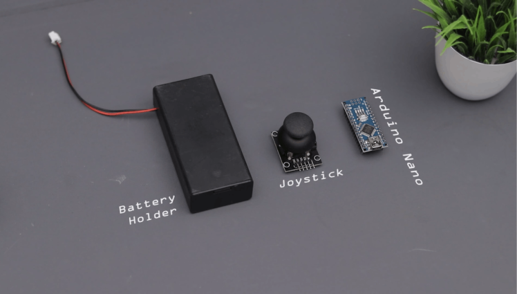
- Arduino (Any board type)
- Jumper wires
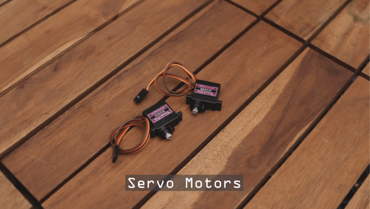
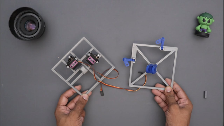
- 2X servo motor 9g
- Joystick module
Tools
- 3D Printer
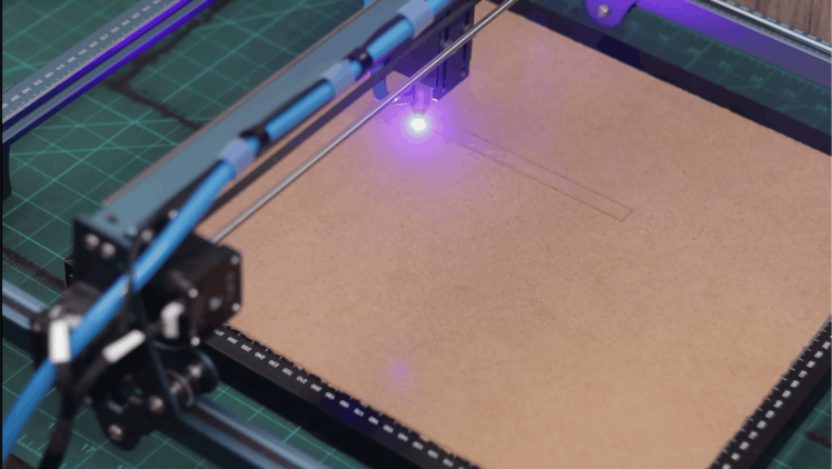
- Laser Cutting
- Hot glue
1 / 4

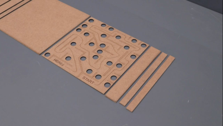
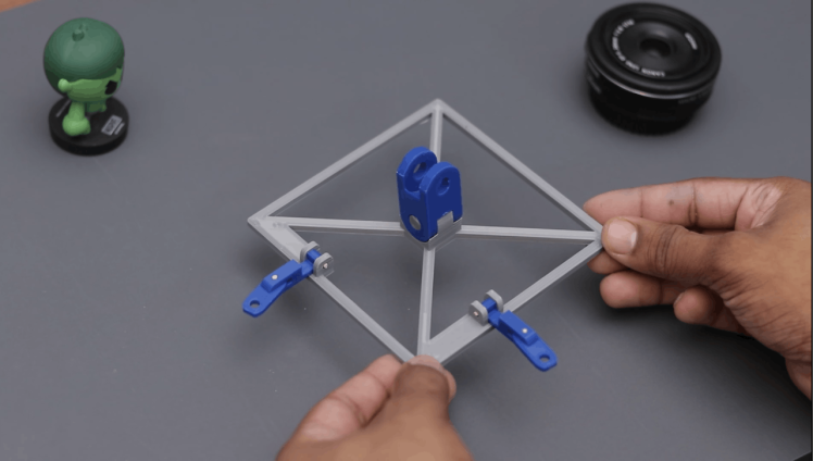
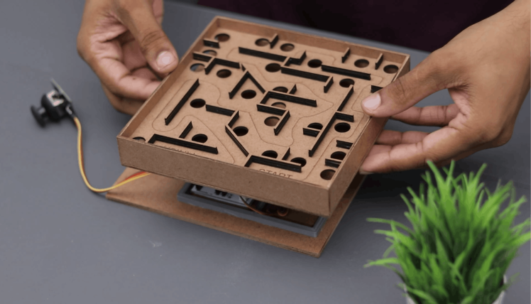
I started designing my Labyrinth maze using sketches to imagine what this game will look like. And I was careful to give it a suitable size and make it pretty easy because kids may also start to build their own maze.
The design files are available to download to make your own game out of the laser-cut files available here.
Print 3D Printed Design1 / 3
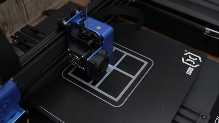
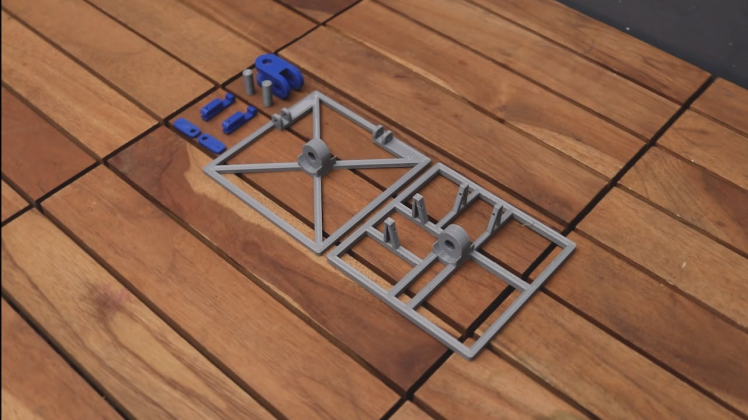
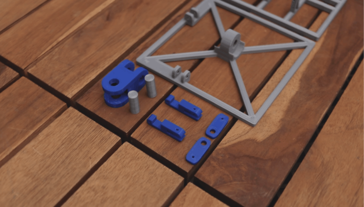
you have to print 6 parts for the gaming maze designed in Autodesk Fusion 360.
Download the. STL files from Here.
I have used 1.75 mm filaments to print the parts. I have printed it in 2 different colours Grey and blue. Y
My settings are:
- Print Speed: 60 mm/s
- Layer Height: 0.2mm
- Fill Density: 25%
- Extruder Temperature: 235 deg C
- Bed Temp: 75 deg C
1 / 7
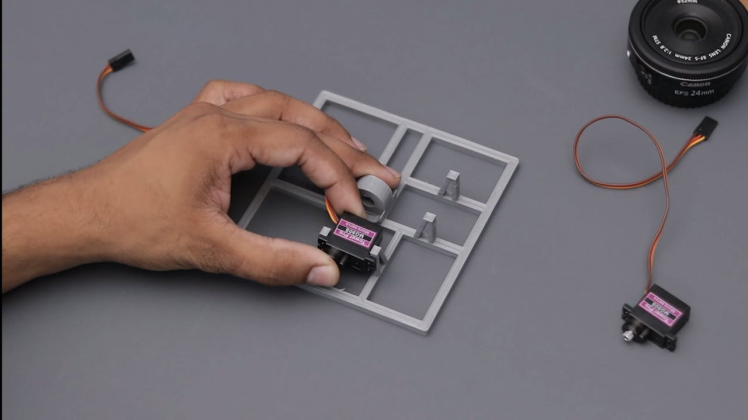
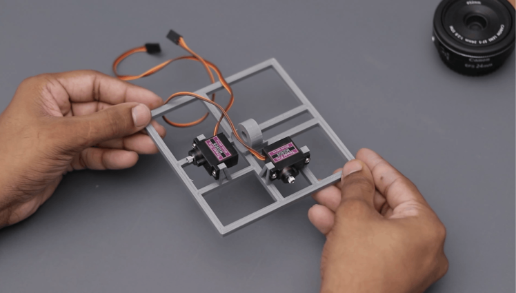

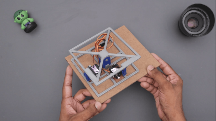
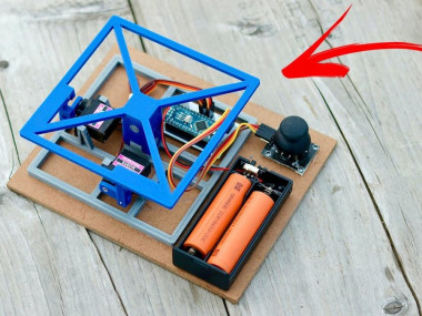
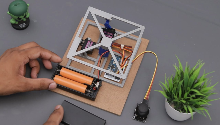
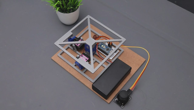
Now you can install all the components to their respective slots. All the parts are installed on the front case.
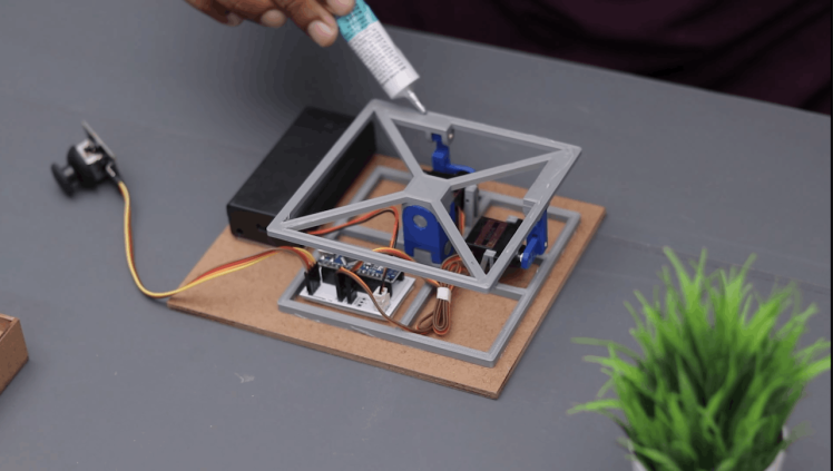
I used hot glue to mount all the parts.
After installing the parts, close the back case and secure the 4 screws at the corner.
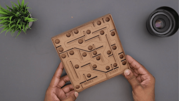
Mounting Laser Cutting Maze1 / 3

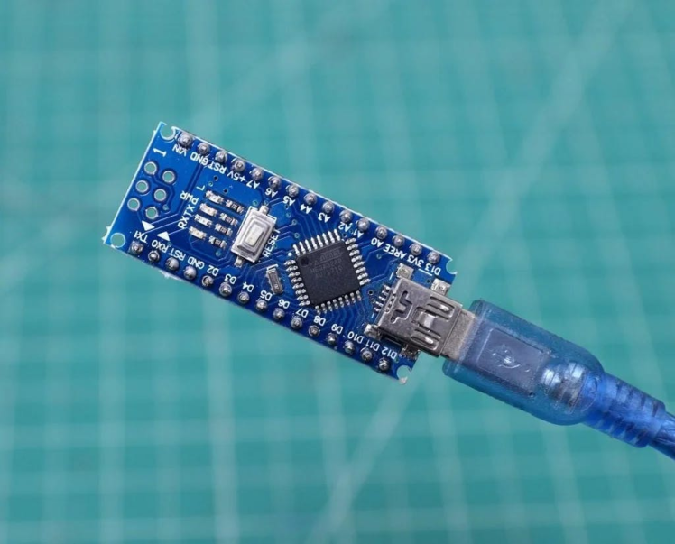
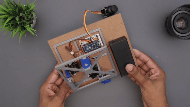
First, download the Arduino sketch from here. Plugin and the USB cable into the Arduino Nano with your laptop or desktop PC.
- Connected your Arduino board to the PC using its USB cable.
- Open Arduino IDE
- Copy the paste the code into a new sketch
Set the correct board and COM Port number and upload the code into the Arduino.
#include <Servo.h>

Servo servo1;
Servo servo2;
int joyX = 0;
int joyY = 1;

int servoVal;

void setup()
{
  servo1.attach(4);
  servo2.attach(3);
}
void loop()
{
  servoVal = analogRead(joyX);
  servoVal = map(servoVal, 0, 1023, 0, 20);
  servo1.write(servoVal);

  servoVal = analogRead(joyY);
  servoVal = map(servoVal,0, 1023, 0 , 20);
  servo2.write(servoVal);
}1 / 3
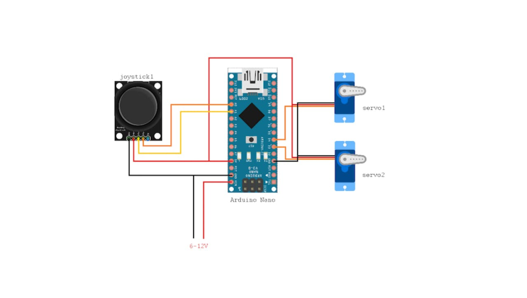
Make the circuit by following the schematic diagram given in the above picture.
Connect the wires of the servos and joystick as shown in the sketch
- Arduino Pin 3 to orange wire in servo 1 (X-axis)
- Arduino Pin 4 to orange wire in servo 2 (Y-axis)
- Red & Brown wires to Arduino 5V and GND
- Arduino Pin A0 to Joystick pin VRx
- Arduino Pin A1 to Joystick pin VRy
- Joystick VCC and GND to Arduino 5V and GND
Make the circuit as per the schematics
VideoIf you enjoyed this article, don’t forget to pass it along!
Follow me for more DIY projects and ideas.
Thank you !!!
Schematics, diagrams and documents
Code
Credits
Related products


Leave your feedback...