

How to Build a Simple DIY Home Automation System

Made by rau7han
About the project
Home automation is a term used to describe the process of automating certain tasks and devices around the home.
Project info
Difficulty: Easy
Platforms: Blynk, ControlEverything.com, NodeMCU, Espressif
Estimated time: 1 hour
License: Creative Commons Attribution-ShareAlike CC BY-SA version 4.0 or later (CC BY-SA 4+)
Items used in this project
Hardware components

Story
Home automation is a term used to describe the process of automating certain tasks and devices around the home. This can include tasks such as turning on the lights when you enter a room or setting the thermostat to a certain temperature. Home automation systems can be as simple or as complex as you like, and there are many different products on the market to suit different needs. In this tutorial, we will show you how to build a simple DIY home automation system using a NODEMCU and a few other components.
Thank You NextPCB:
This project is successfully completed because of the help and support from NextPCB. Guys if you have a PCB project, please visit their website and get exciting discounts and coupons.
- Only 0$ for 5-10pcs PCB Prototypes:https://www.nextpcb.com
- Free shipping 0$ PCB Prototype:https://www.nextpcb.com/?code=Romeohacker
- 4-layer PCB price reduction up to 40%: nextpcb.com/40%off
you can monitor and control your home’s energy usage, security system, and much more.
The NodeMCU system is easy to install and use, and it’s compatible with a variety of home automation devices and appliances.
Introduction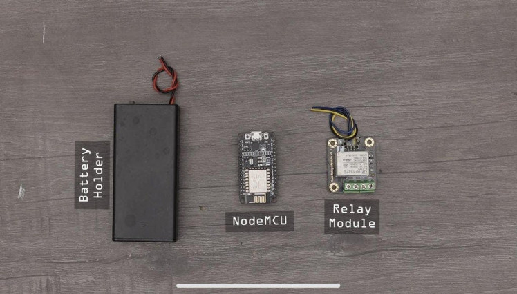
Nowadays, home automation is becoming increasingly popular as it can offer homeowners a lot of benefits. Home automation can be defined as a system that automates and controls various home appliances and devices automatically. For example, it can turn on the lights when you enter the room or turn off the TV when you leave the room. It can also adjust the temperature of the room automatically based on the weather outside.
Nodemcu is a very popular home automation system. It is straightforward to use and it has many features. It can control the lights, windows, doors, and many other things in your house. It is very convenient and it can save a lot of time.
What Is Nodemcu?
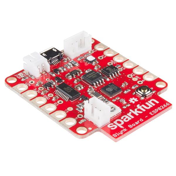
NodeMCU is a development board based on the ESP8266 12-E chip. It has on-board WiFi and can be programmed using the Arduino IDE. NodeMCU is an open-source project and has been developed by the community.
A nodemcu board is a microcontroller board that uses the Lua programming language. It is based on the ESP8266 Wi-Fi chip and has built-in flash memory, making it ideal for use in IoT applications. The board can be programmed using the Arduino IDE
How Nodemcu Can Be Used for Home Automation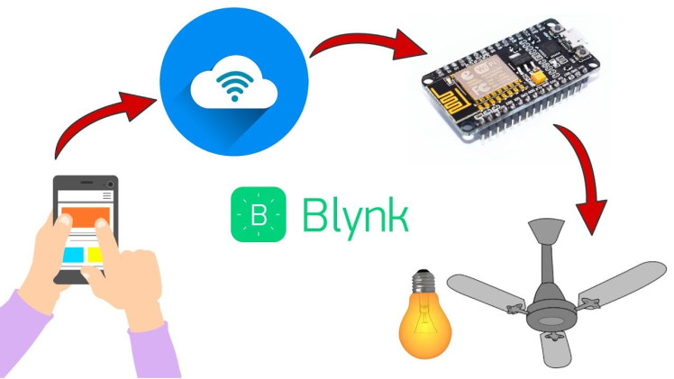
Nodemcu can be used for home automation in a few different ways. One way is to use it as a central controller for all of your devices. You can program it to turn on and off lights, appliances, and other devices. You can also use it to monitor energy usage and control temperature and humidity levels.
Another way to use nodemcu for home automation is to use it as a security system. You can program it to notify you if there is a break-in or if someone is trying to enter your home. You can also use it to monitor activity around your home and to record video footage.
Finally, you can use nodemcu to create a home automation system that is completely customised to your needs.
Nodemcu is a versatile platform that can be used for a variety of home automation applications. With a little creativity, you can use it to create a system that is perfect for your home and your family.
Circuit Diagram & Connection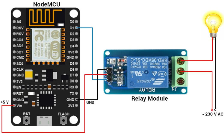
The circuit diagram for Blynk Controlled Home Automation using NodeMCU is given Above. Using this circuit diagram you can assemble the circuit on a breadboard using 4 channel Relay and NodeMCU Board.
Build Circuit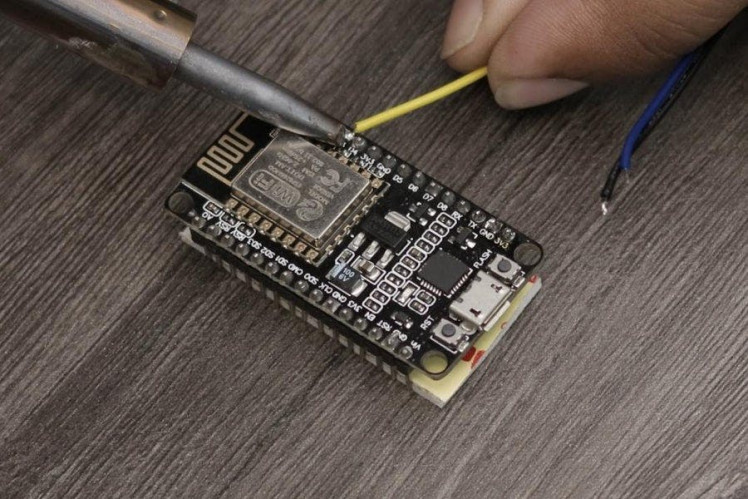
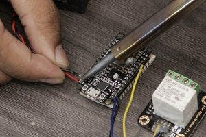

1. Now According to the Pin diagram mapping of the Esp8266 board
2. The connection is pretty simple just connect the Led to the D7 pin
Home Automation PCB & Gerber File1 / 2
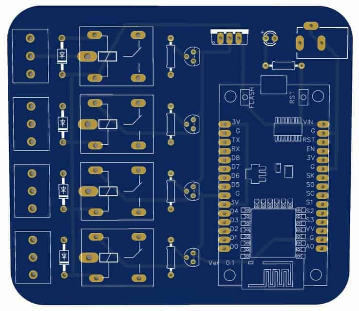
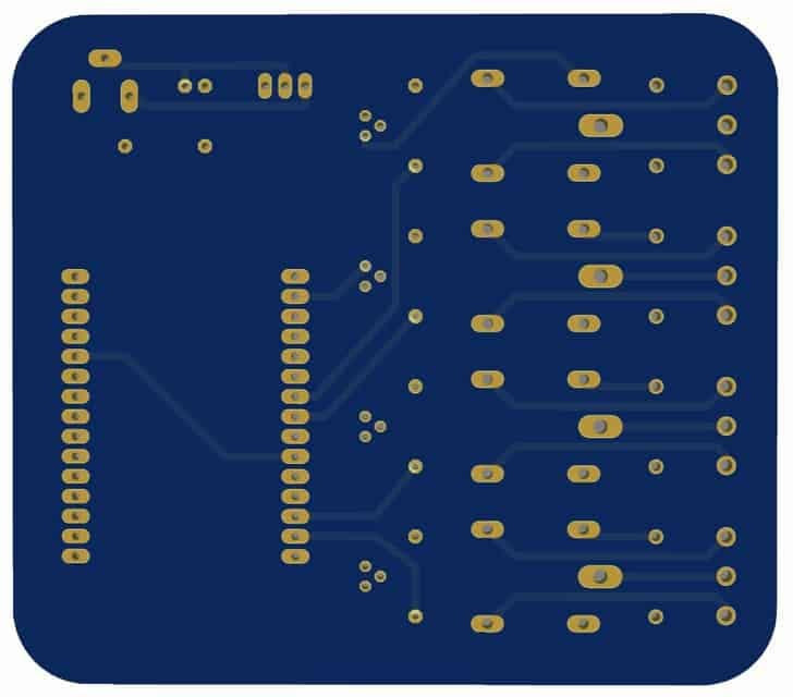
If you don’t want to assemble the circuit on a breadboard and you want PCB for the project, then here is the PCB for you. The PCB Board for the Home Automation Project is designed using EasyEDA online Schematics & PCB designing tool. The front side and back side of the PCB are given above
You can simply download the Gerber File from here.
Setting Up Blynk Application1 / 5
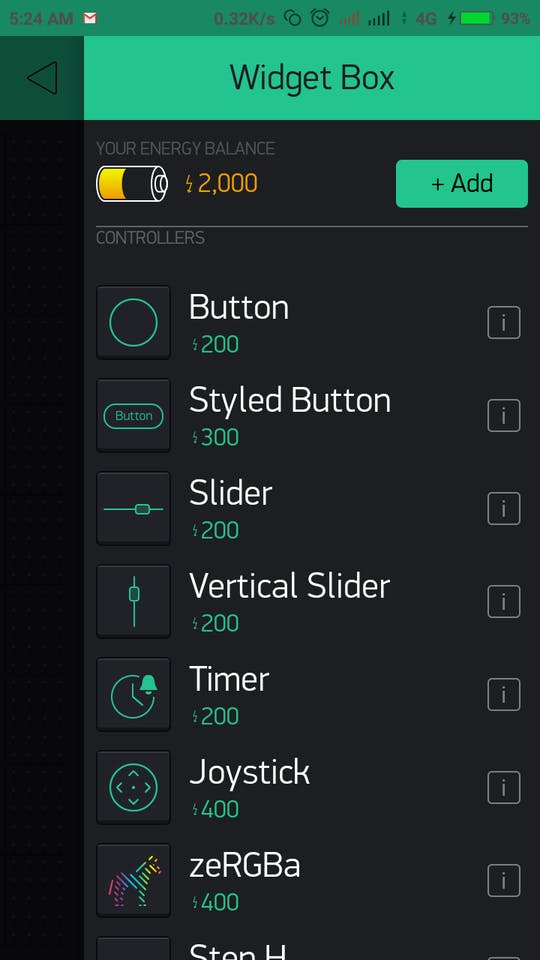
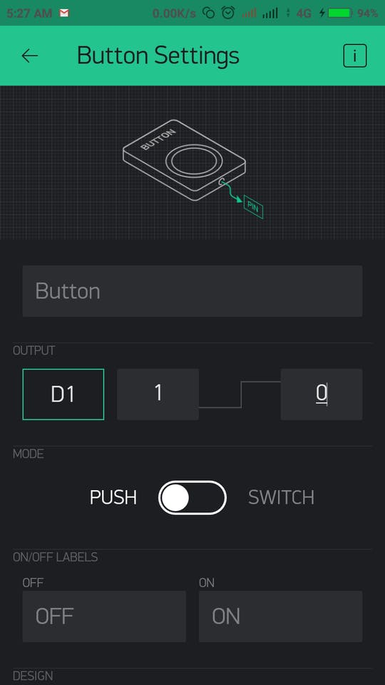
Blynk is a platform with iOS and Android apps that allows you to control your Arduino, Raspberry Pi, or ESP8266 from your mobile phone. You can create a project in the Blynk app and add a variety of Widgets to it. Widgets can be buttons, sliders, graphs, or even a terminal. Each Widget has a unique function that can be configured. For example, you can configure a button to turn an LED on and off.
Blynk makes it easy to control your hardware from your mobile phone. With Blynk, you can create complex projects with ease. The Blynk app is easy to use and is packed with features. With Blynk, you can control your hardware from anywhere in the world.
To Install the Blynk app on your smartphone
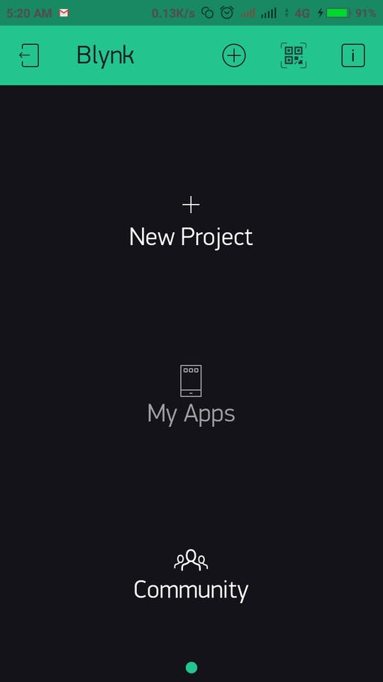
Set up Blynk App:Step 1: Download Blynk from PlayStore.
Step 2: Register with an email ID where you will receive an“Auth Token”.
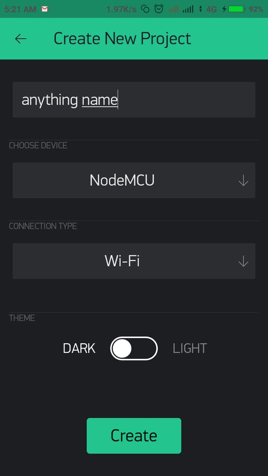
Step 3: Open New Project and name the project.
Step 4: Choose device “ESP8266”. Click on create.
Step 5: After creating aproject you will receive mail, which contains “Auth_Token”.
Step 6: Copy this “Auth_Token” and paste into our Arduino Code.
char auth[] = "YourAuthToken";
char auth[] = "YourAuthToken";
Make sure before uploading the code, add your SSID and password.
Source CodeHere is a Simple DIY Home Automation System Code, you can copy the code and paste it in your Arduino IDE. But before that, you need to add Blynk Library to Arduino IDE.
Download Blynk Library from here: https://github.com/blynkkk/blynk-library or SKETCH -> INCLUDE LIBRARY -> MANAGE LIBRARIES -> SEARCH FOR "Blynk" -> INSTALL THE LIBRARY
Then go to File->Eamples->Blynk-Boards_Wifi->Esp8266Standalone
Select the correct board (NodeMCU 1.0) and the com port from the Tools Menu
Finally, Save the file and Press Upload
#define BLYNK_PRINT Serial
#include <esp8266wifi.h>
#include <BlynkSimpleEsp8266.h>
/// You should get Auth Token in the Blynk App.
// Go to the Project Settings (nut icon).
char auth[] = "YourAuthToken";
// Your WiFi credentials.
// Set password to "" for open networks.
char ssid[] = "YourNetworkName";
char pass[] = "YourPassword";
void setup()
{
  // Debug console
  Serial.begin(115200);
  Blynk.begin(auth, ssid, pass);

}
void loop()
{
  Blynk.run();
}
1. After uploading the code
2. Open the Blynk app on the Phone
3. Let it connect to the internet
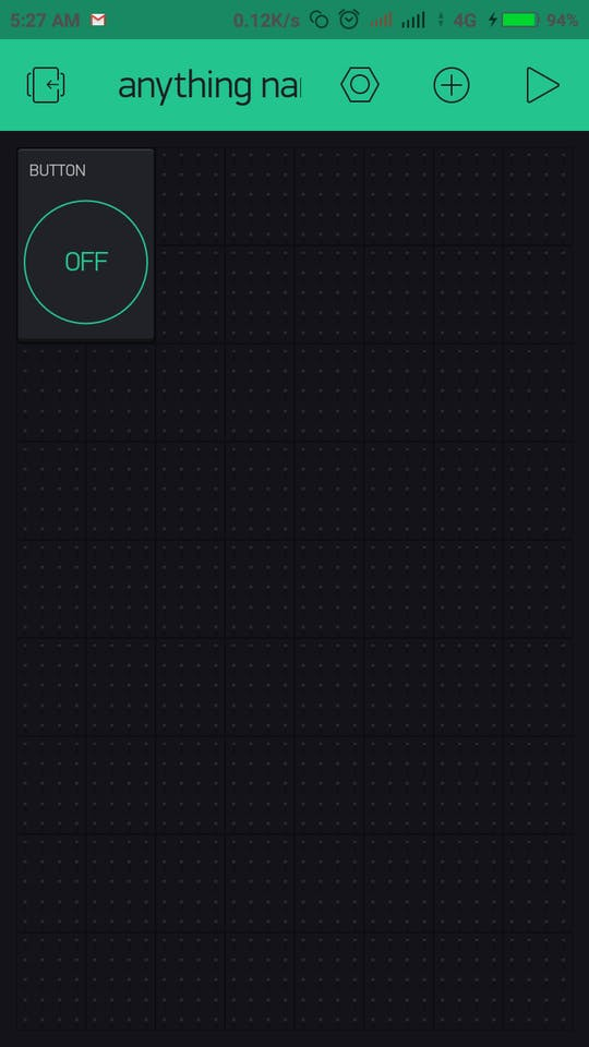
4. Then you would see your dashboard with a button
5. Press thePlay button on the top most right corner of the app
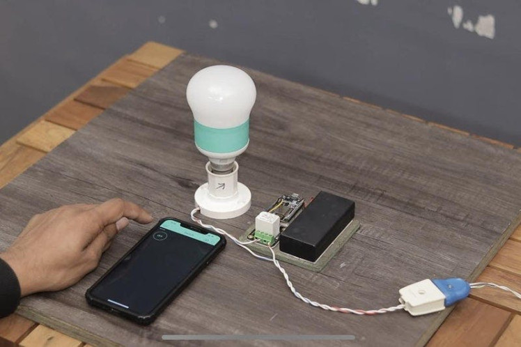
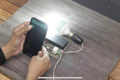
6. Then press the button and you would see the LED Turn ON!!!:)
Now that you have got the basics, you can try some cool stuff with this awesome board !!
I will really appreciate it if you share your valuable feedback. Also if you have any queries please write in the comment section. Have fun exploring this board :)
Happy Inventing!!, Next week with more interesting projects:
Schematics, diagrams and documents
Code
Credits
Related products


Leave your feedback...