
Hello Isp Board

Made by Rashidt
About the project
Let's make some open design, and open hardwareRequired Materials:ATTiny45resistors - 100 ohm (2) ,499 ohm , 1k , 10kcapacitors - 1uf,10pf...
Project info
Items used in this project

Story
Let's make some open design, and open hardware
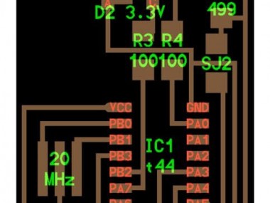
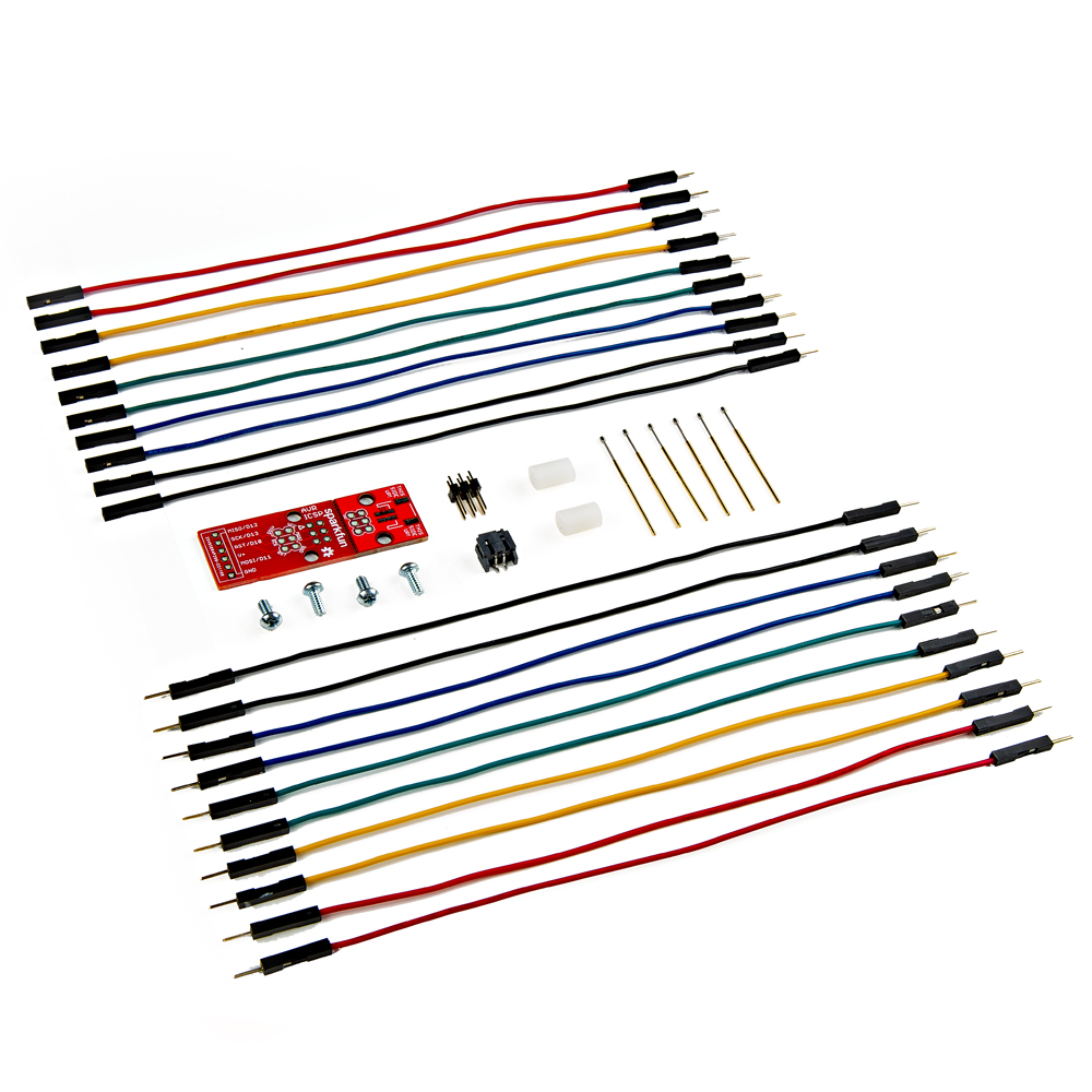
Required Materials:
ATTiny45
resistors - 100 ohm (2) ,499 ohm , 1k , 10k
capacitors - 1uf,10pf(2)
diodes - 3.3 v (2)Cristal - 20MHz
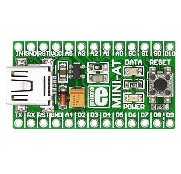
- j2 USB
if you need CAD file Downloaded CAD file of board designs from below
hello.ISP.44.cad
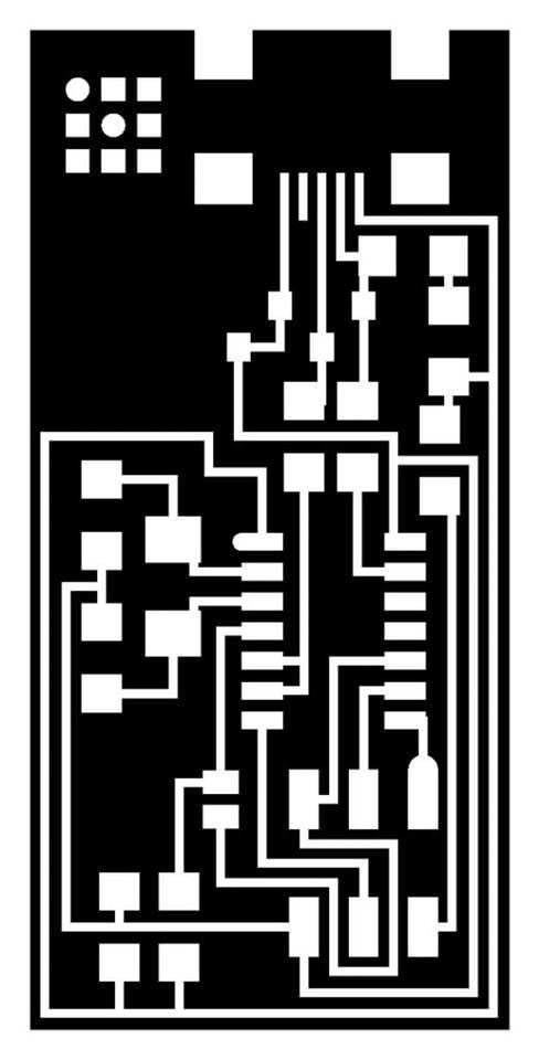
or direct download .png file of circuit for printing PCB
Step 1: Get the CAD file
1 / 3


if you need CAD file Downloaded CAD file of board designs from below
hello.ISP.44.cad
CAD file of board or direct download .png file of circuit for printing PCB
Step 2: Preparing the Roland Modela & print the board
1 / 3
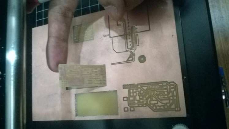
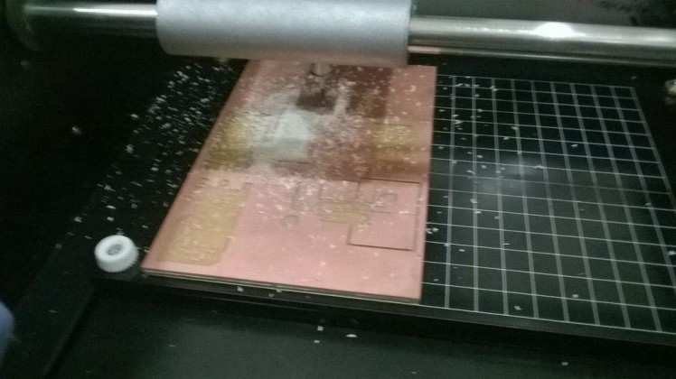
Roland Modela is used for milling the circuit board.
CAD file open it in Antimony got the Trace .png and Outline .png. (or directly downlode .png format files)
The next step is to open Fab Modules and give .png as the input format, select modella as the machine. Then load the traces .png file and then make path. Leave the settings as default.
Now move onto the machine. Switch it on. Change the bit carefully to 1/64 for milling the traces. Using the Fab Module move the head to the point where you want the origin to be. Then correct the height of the bit. We want to have it just touching the surface.
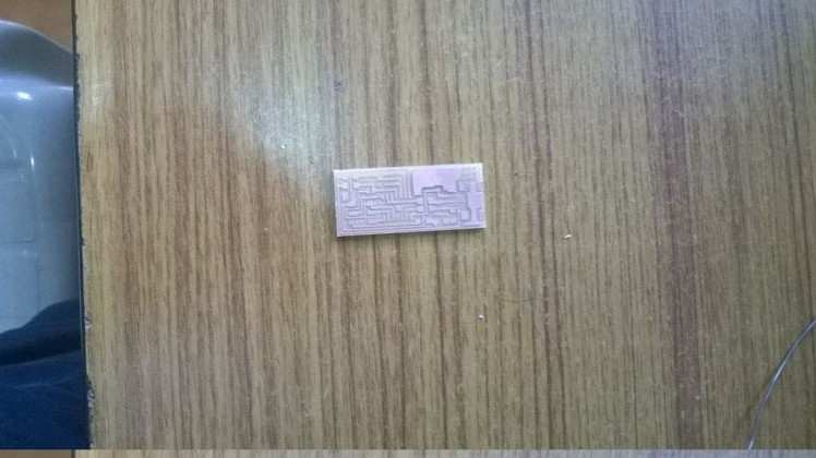
Now in the Fab Modules give make .rml command and then send it to modella. Wait till the work is done. After cutting the traces change the bit to 1/32 and repeat the process using Fab Modules using cut board .png fil. This will make a cut around our circuit so that we can remove it from the larger board.
Note: Be careful while removing the board as their are chances of damaging it.
Step 3: Solder Electronic Components
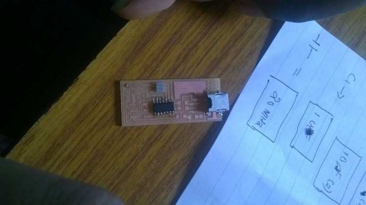
Now as we have the board, it’s time to start soldering the components to
it. As a good practice, write down the components in a paper/book and draw a box corresponding to each component. Then we took the components and placed them in their corresponding boxes. This way we won’t mix up anything and it,s easy to solder as the components are kept handy.
After soldering we have to check under the magnifier if the connections are proper and if time allows, do a continuity check too.
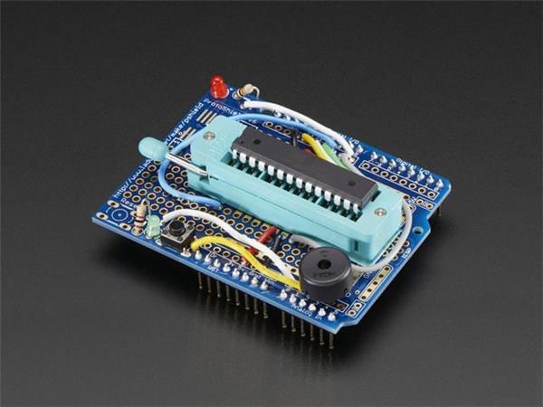
Step 4: Programming the Board
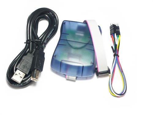
The prerequisites for programming your board are
- latest version of avr dudea
- mini USB cable
- the firmware of the board
When you have all the above try to flash the Firmware into the board. The steps to be followed are
- download and extract the firmware
- open a terminal over there and give the following commands
- make clean
- make hex : If you are using an Atmelice isp make that change in the makefile [change to atmelice_isp]. If you are using USB tiny then change to that.
- sudo make fuse : initially it may show some error. But try it multiple times and you will probably succeed.
- sudo make program .
After doing all the above without any error messages popping up, your board should be programmed to work as an ISP.
Note: a soldering jumper should be removed after flashing the firmware
Credits
Related products


Leave your feedback...