
Hc-05 Bluetooth With Raspberry Pi Pico Using Micropython

Made by rau7han
About the project
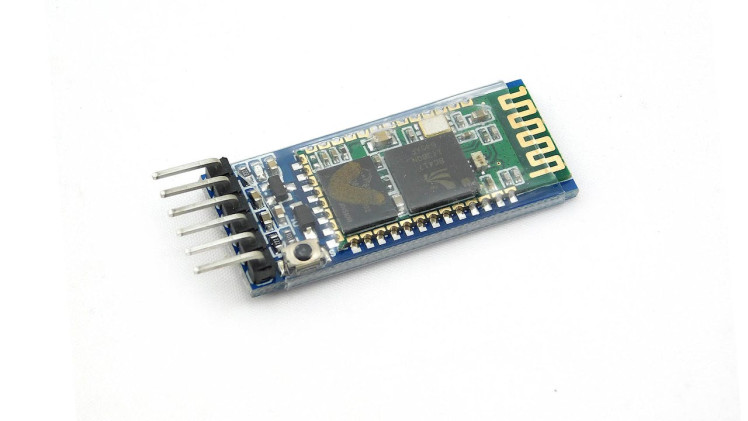
This guide covers how to use the HC-05 Bluetooth module with a Raspberry Pi Pico board using MicroPython. The HC-05 is a Bluetooth module.
Project info
Difficulty: Easy
Platforms: Raspberry Pi
Estimated time: 1 hour
License: Creative Commons Attribution-ShareAlike CC BY-SA version 4.0 or later (CC BY-SA 4+)
Items used in this project

Story
This guide covers how to use the HC-05 Bluetooth module with a Raspberry Pi Pico board using MicroPython. The HC-05 is a Bluetooth module that can be used to wirelessly communicate with other Bluetooth devices, such as smartphones, laptops, and other microcontrollers.
Thank You NextPCB:
This project is completed with amazing success thanks to NextPCB support. If you have any PCB projects please visit their website to get attractive discounts.
- Only 0$ for 5-10pcs PCB Prototypes:Nextpcb.com/pcbprototype
- Register and get $100 from NextPCB: Nextpcb.com/coupon
Why NextPCB
- Most Efficient, Economic, Innovative PCB Solutions
- Higher Quality
- Lower Cost
- Faster Delivery
We'll go over how to set up the HC-05 and how to use it with a Raspberry Pi Pico.
Components Required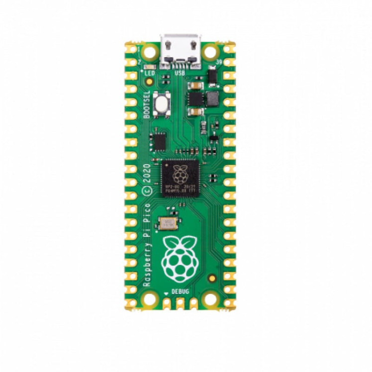
You need to ensure that you have the following components below before going through this tutorial.
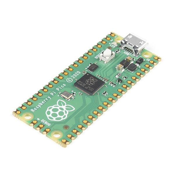
- Raspberry Pi Pico
- HC05 Bluetooth Module
- Jumper Wire
- Breadboard
1 / 3
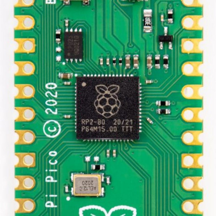
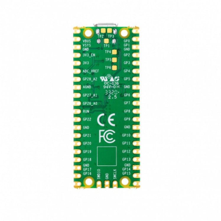

Raspberry Pi Pico is a newly launched microcontroller by Rasberry Pi. Its tiny, fast, and versatile microcontroller board is based on an RP2040 chip designed by Raspberry Pi. Pico is a low-cost and flexible development platform with the below specifications.
Specifications :- RP2040 microcontroller chip designed by Raspberry Pi
- Dual-core Arm Cortex-M0+ processor, flexible clock running up to 133 MHz
- 264KB on-chip SRAM
- 2MB on-board QSPI Flash
- 26 multifunction GPIO pins, including 3 analogue inputs
- 2 × UART, 2 × SPI controllers, 2 × I2C controllers, 16 × PWM channels
- 1 × USB 1.1 controller and PHY, with host and device support
- 8 × Programmable I/O (PIO) state machines for custom peripheral support
- Supported input power 1.8–5.5V DC
- Operating temperature -20°C to +85°C
- The castellated module allows soldering directly to carrier boards
- Drag-and-drop programming using mass storage over USB
- Low-power sleep and dormant modes
- Accurate on-chip clock
- Temperature sensor
- Accelerated integer and floating-point libraries on-chip
Getting Started Raspberry Pi Pico – Pinout, Specs – Beginner Guide
Raspberry Pi Pico Pinout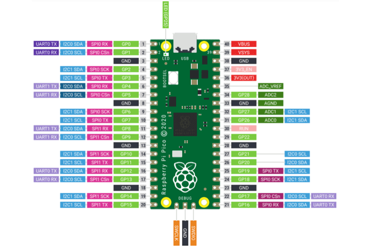
1 / 2

- Press and hold the BOOTSEL pin then plug in the USB port to the PC.
- Download the Micropython UF2 file by clicking the below link.
- Release the BOOTSEL pin once connected pico is connected to the PC.
- It will mount as mass storage named "RPI-RP2"
- Drag and drop the downloaded micro python UF2 file on RPI-RP2 storage, it will reboot automatically the pico board.
- your pico is now running micropython.
Download the UF2 file From Micropython Official Site
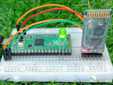
Circuit Diagramdiyprojeectslab.com/raspberry-pi-projects

diyprojeectslab.com/raspberry-pi-projects
The circuit diagram of the Raspberry Pi Pico and Bluetooth module is very easy. VCC and GND pins of the HC05 Bluetooth module are connected with the Raspberry Pi Pico 3.3V and GND pins. TXD and RXD pins of the Bluetooth module are connected with the GP0 and GP1 pins of the Raspberry Pi Pico.
Vcc -------> 3.3V or 5V
GND --------> GND
RX ----------> GPIO 0
TX ----------> GPIO 1
Micropython Code - Bluetooth Module With Raspberry Pi PicoCopy the following code and paste it into the IDE. Check Also Getting Started With Raspberry Pi Pico With Thonny IDE Check How to use thonny IDE with Raspberry Pi Pico
Main.py#Diyprojectslab.com
from machine import Pin, UART
uart = UART(0, 9600)
led = Pin(13, Pin.OUT)
while True:
if uart.any() > 0:
data = uart.read()
print(data)
if "on" in data:
led.value(1)
print('LED on n')
uart.write('LED on n')
elif "off" in data:
led.value(0)
print('LED off n')
uart.write('LED off n')You need to download the Serial Bluetooth Terminal App from the Google Play store and install it on your smartphone.
Conclusion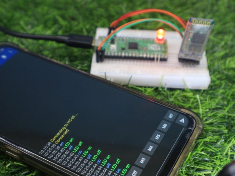
Finally, we check every command received from the Android phone and then turn the ON and turn OFF the LED. It shows everything is working properly. now we are done here.
See Working Video
Thanks!
Schematics, diagrams and documents
Code
Credits
Related products


Leave your feedback...