
Easy Programming STM32F407 Discovery Board with mbed

Made by electrouser805
About the project
A quick start guide to program STM32F407 Discovery Board with mbed online IDE.
Project info
Difficulty: Easy
Platforms: Arm Mbed
Estimated time: 1 hour
License: Apache License 2.0 (Apache-2.0)
Items used in this project

Story
Why?
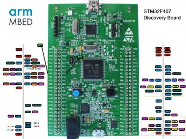
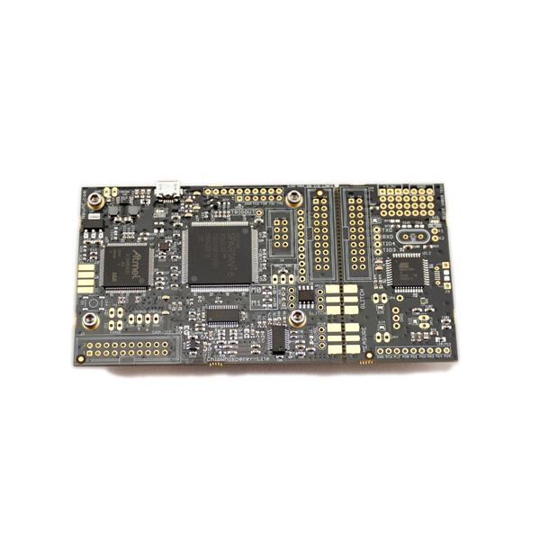
STM32F407 Discovery board does not directly support MBED online IDE. But the mcu on this board is also used in another official MBED board ( Seeed Studio Arch Max v1.1 ) . So, it is possible to program Discovery board by treating it as an Arch Max board.
- It's an easy way for rapid prototyping with online IDE of MBED. No need to install Keil/IAR/AC6 on PC and go through painful setup.
- Common things like ADC/PWM/DAC/GPIO/UART/SPI/I2C can be used with minimum configuration.
- On board accelerometer is also tested.
Attached code below demonstrates all these functionalities.
Step 1: Go to mbed.org and login/signup
 mbed.org
Step 2: Select Platform Seeed Arch Max
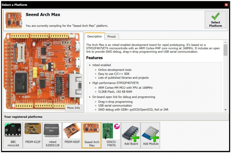 Selecting platform
Step 3: Edit, Compile and Download Code
Following code demonstrated GPIO, ADC, Serial, PWM and On board Accelerometer capabilities
Library:
#include "mbed.h"
#include "LIS3DSH.h"
GPIO and Pwm Initialization:
DigitalOut rLED(PD_14);   // on board red LED, DO
DigitalOut bLED(PD_15);   // on board blue LED. DO
DigitalOut gLED(PD_12);   // on board green LED, DO
DigitalOut oLED(PD_13);   // on board orange LED, DO
PwmOut GLED(PA_9);        // on board green LED,
PWMDigitalIn  pbSW(PA_0);    // on board blue PUSH Switch, active high DI
Serial and ADC:
Serial serial(PA_2,PA_3); // serial com tx, rx UART
AnalogIn   adcPB0(PB_0);  // PB0 as 12 bit ADC
Serial baud and print:
  // set serial baud and print welcome msg //
serial.baud(19200);
serial.printf("Welcome to STM32F407 Development with mbedOS nr");
PWM Frequency and Duty Cycle:
GLED.period(1.0f/freq);  // set pwm period
GLED.write(duty/100.0f); // set pwm duty cycle
LED Blink:
 rLED = 1;
 gLED = 1;
 wait(delay);
 rLED = 0;
 gLED = 0;
 wait(delay);
ADC Read:
  // adc value read //
  adcval = 4095*adcPB0.read_u16()/65535; // 12 bit value
Pins shared with on board hardware
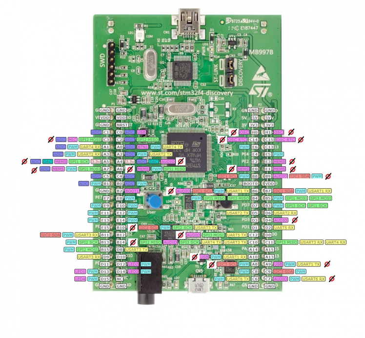 "Not-Marked" pins are not recommended to use, these might interfere with on board hardwares
Update 1: DAC works on PA4 and PA5
Just tested 12 bit DAC on A4 and A5 pins. It works. But, Accelerometer and Audio might not be used along with DAC for other application (same pin).
DAC Setup:
// Before main
AnalogOut dac1(PA_5);
AnalogOut dac2(PA_4);
Output Analog Voltage:
// set up 1 volt on dac 1
dac1 = 0.333f; // vdd* 0.333 = 3.0*0.333 =  1.0 volt
// set up 1.5 volt on dac 2
dac2 = 0.5f; // vdd*0.5 = 1.5 volt
Update 2: 20x4 LCD support
Tested lcd display with mbed, working great ! 5 volts display runs with 3.3 v logic without issues. Code link will be added after final testing.
Caveats
Not all functions will work according to above pin map. For example Pwm on PD13 will not work on mbed. Because, mbed compiler treats the code according to Arch Max boards pin mapping.
For, pin specific function that will work for sure, see the pin map attached below.
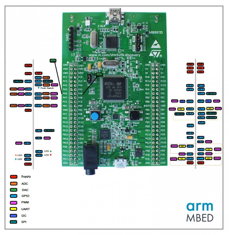 Based on Arch Max Pin Mapping (download schematic below for better image)
External Resources
Schematics, diagrams and documents
Code
Credits
Related products


Leave your feedback...