
CO2 Shield2Go
Made by Infineon Technologies
About the project
It's about time you add CO2 sensing to your project and here's how :)
Project info
Items used in this project
Hardware components

Story
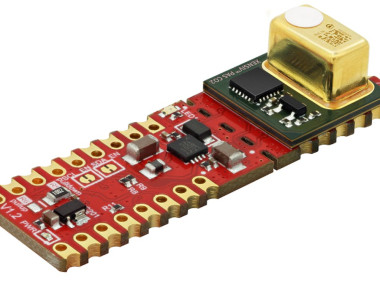
The XENSIVTM PAS CO2 is a real CO2 sensor in an exceptionally small form factor based on the photoacoustic spectroscopy (PAS) principle. The principal of measuring the CO2 concentration is based on using Infineon's MEMS (Micro-Electro-Mechanical Systems) Microphone, which detects the pressure change generated by CO2 molecules within the sensor cavity. CO2 concentration is then delivered in the form of a direct ppm readout thanks to the integrated microcontroller. Highly accurate CO2 readings are guaranteed.
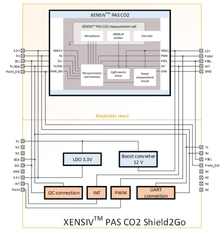
Pinout

Pinout
5V 5V supply input.SDA I2C SDA (serial data).SCL I2C SCL (serial clock).GND Supply and signal ground.3.3V 3.3V supply input - use as logic supply when using breakable part stand-alone, else keep NC.INT Interrupt output.PWM PWM signal output.TX UART transmit side.RX UART receive side.PSEL Communication interface selection. High level selects UART and low level selects I2C. It is recommended to the user to hard wire the pin to VDD or GND, depending on the wanted interface PWM DIS PWM disable input (set high to disable PWM).12V 12V supply input - use as sensor supply when using breakable part stand-alone, else keep NC.TX/SDA UART transmit or I2C SDA (serial data), depending on selected communication interface.SWD Serial wire debug data (keep NC).SWCLK Serial wire debug clock (keep NC).
Note: PSEL and PWM_DIS are both by default connected to GND on board of XENSIV PAS CO2 Shield2Go.
CRASH COURSE: How do microphones work?
In physics, sound is a vibration that propagates as an acoustic wave, through a transmission medium such as a gas, liquid or solid. -Wikipedia.
Microphones measure the vibration of air molecules and through digital to analog converters these vibrations are converted to bits.
The PAS principle works as follows. Pulses of light from an infrared source pass through an optical filter tuned specifically to the CO2 absorption wavelength (λ= 4.2 µm). The CO2 molecules inside the measurement chamber absorb the filtered light, causing the molecules to shake and generate a pressure wave with each pulse. This is called the photoacoustic effect. The highly sensitive MEMS acoustic detector detects the pressure change generated by CO2 molecules within the sensor cavity, and the microcontroller converts the output into a CO2 concentration reading. In order to achieve a ppm reading as accurate as possible, the acoustic detector is optimized for low frequency operation, and the absorption chamber is acoustically isolated from external noise.

The XENSIVTM PAS CO2 Shield2Go includes every necessary component to fully supply the XENSIVTM PAS CO2 with all the available features enabled and optimized. The necessary stable 12 V supply for the IR emitter is generated on board with a DC/DC boost converter and also an LDO for the 3.3 V supply is integrated on board which reduces the required supplies to a single 5V supply. If you want to use your own design it is possible to break the headof the shield apart. This only consists of the XENSIVTM PAS CO2 module with all the pins routed out on castellated pads to easily mount the XENSIVTM PAS CO2 to other PCBs. PWM and INT functionality is also covered in both cases.
Two communication interfaces are available. By default, the I2C interface is configured but with a simple rearrangement from the pull-up resistor R5 to pull-down resistor R6, the UART interface can be selected. To fully disable the I2C interface and the connected pull-up resistors on the SDA/Tx and SCL lines solder jumpers can be cut and disconnected.
ConnectionsTo use the PASCO2 shield2go you could either:
- attach it directly on top of an XMC2GO micro controller and connect it to an external 5V supply (in case you're using the XMC2Go V1.0 boards.)
Note: new XMC2GO boards have a 5V pin included. This photo was taken on a V1.0 model.

Note: new XMC2GO boards have a 5V pin included. This photo was taken on a V1.0 model.
- simply stack them up onto a MY IOT adapter (feel free to check out its protip here). Use the My IOT adapter on top of any microcontroller using an Arduino Uno pinout.NOTE: when using the MYIOT adapter make sure to use it on a microcontroller with a reference voltage of 5V, since we need it for the operation of our PAS CO2 Sensor. Boards like the Arduino Uno, Due or XMC 4700 Relax kit should do the trick :)
MY IOT Adapter on Arduino Uno

MY IOT Adapter on Arduino Uno
- Of course you can also manually connect every single connection to your microcontroller of choice.
Connections with an Arduino Due

Connections with an Arduino Due
Connections with anXMC2GO V1.0 board

Connections with anXMC2GO V1.0 board
Operation Modes
As shown in the diagram above the PASCO2 sensor has three operation modes:
•Idle mode: The device does not perform any CO2 concentration measurement. The device remains inactive until it becomes active shortly to serve interrupts before going back to an inactive state.•Continuous mode: In this mode, the device periodically triggers a CO2 concentration measurement sequence. Once a measurement sequence is completed, the device goes back to an inactive state and wakes up automatically for the next measurement sequence. The measurement period is programmable from 5sec to 4095 sec. •Single-shot mode: In this mode, the device triggers a single measurement sequence. At the end of the measurement sequence, the device goes back automatically to idle mode.
SoftwareNow that we're familiar with our system, let's look at how we could actually use it. First thing's first - let's install all the software needed:
- Install Arduino IDE. If you are new to Arduino, please download the program and install it first.
- Install XMC Board. The official Arduino boards are already available in the Arduino software, but other third party boards as the Infineon XMC MCU based need to be explicitly included. Follow the instructions in the link to add the XMC board family to Arduino.
- Install the sensorlibrary. In the Arduino IDE, go to the menu Sketch > Include library > Library Manager. Type pas-co2-sensor and install the library.

Now that we've got all the prerequisites in check, let's dig in!To start with for using our library we need to always include it along with the basic Arduino library at the top of our code :
#include <Arduino.h>
#include <pas-co2-ino.hpp>
Additionally we will have to instantiate an object of type PASCO2Ino to define our desired sensing functionality, let's say we'll call it cotwo:
PASCO2Ino cotwo;The last step to do before getting our hands dirty is to create an error type variable and a 16 bit integer to store our sensor readings. (The error type variable will be used as an error monitoring buffer, where we will be monitoring its value to make sure that everything is working properly):
int16_t co2ppm;
Error_t err;
By now the question that we have to ask our self is: How do we actually want the sensor to talk to us? To answer that we would have to look at the two possibilities which are UART and I2C (since the PASCO2 sensor supports both).
To use I2C simply initialize an I2C interface to be used by the sensor by:
Wire.begin();
Wire.setClock(400000);
(In the code snippet above I used a frequency of 400000 since it is the maximum frequency that the sensor supports. The sensor supports a range of values between 100KHz to 200KHz).
To use UARTsimply initialize a UART interface to be used by the sensor by:
Serial.begin(9600);Where the maximum baudrate supported by the sensor is 9.6kBps.
NOTE: You could have a UART and an I2C interface open by your system at the same time so that you could for example read the sensor readings through I2C and send them to your PC through UART :)
Next step is to actually initialize our sensor, we do this by using the begin( ) function on our created instance of the PASCO2Ino object we created. Here proves the error type variable itself handy. We will use it to check that the initialization was performed successfully:
err = cotwo.begin();
if(XENSIV_PASCO2_OK != err)
{
Serial.print("initialization error: ");
Serial.println(err);
}
Error Macros:
Result code indicating a successful operationXENSIV_PASCO2_OK (0)Result code indicating a communication errorXENSIV_PASCO2_ERR_COMM (1)Result code indicating that an unexpectedly large I2C write was requested which is not supportedXENSIV_PASCO2_ERR_WRITE_TOO_LARGE (2)Result code indicating that the sensor is not yet ready after resetXENSIV_PASCO2_ERR_NOT_READY (3)Result code indicating whether a non-valid command has been received by the serial communication interfaceXENSIV_PASCO2_ICCERR (4)Result code indicating whether a condition where VDD12V has been outside the specified valid range has been detectedXENSIV_PASCO2_ORVS (5)Result code indicating whether a condition where the temperature has been outside the specified valid range has been detectedXENSIV_PASCO2_ORTMP (6)Result code indicating that a new CO2 value is not yet readyXENSIV_PASCO2_READ_NRDY (7)
AND NOW to the most important function of the library startMeasure( ), this function is what dictates the whole functionality of our sensor. The input parameters of this function decide the mode used where:
- no input parameters: single shot mode
- measuring interval in seconds: continuous mode
- measuring interval in seconds, PPM threshold, and Pointer to the callback function to be called upon interrupt: alarm mode
- measuring interval in seconds, 0, and Pointer to the callback function to be called upon interrupt, true: early notification mode
Alarm mode: If the alarm threshold argument is non-zero, the alarm mode is activated, and the sensor internal flag will be enabled if the concentration of CO2 goes above the specified value. This option is better combined with the interrupt mode. Thus, if the interrupt mode is available and a callback function is passed, the interrupt will occur only when the co2 concentration goes above the threshold. This makes mostly sense for continuous measurement configuration. But it can be used as well for a single shot configurationEarly notification: The early notification mode can be used for battery power solutions. The interrupt signal can trigger the enablement of the 12V emitter power supply just before the measurement is performed, and switch it off as the interrupt signal is disabled. Therefore, the power supply 12V only needs to be on during the CO2 sensing. (Note in case of the early notification mode the callback fed in the startMeasure() function is executed every time that the sensor is about to start performing the measurement and when it is completed.When this flag is set, the alarm interrupt functionality is not available. Both options cannot be combined.
The second most important function is the getCO2( ) function. This function takes in our 16 bit integer variable that we created earlier, stores the new CO2 PPM value and then gives back an error type value.
The CO2 concentration value acquired by the sensor is dependent on the external atmospheric pressure. To compensate for this effect, the application system can provide the value of the atmospheric pressure by using the setPressRef( ) function. At the end of a measurement sequence, the device reads the pressure value and applies for compensation on the CO2 concentration value before storing it into the result registers. The setPressRef( ) function takes in a value between 750to 1150 hPa. A good act would be to have a pressure sensor, like our DPS310 or DPS368 that keeps monitoring the pressure values and refeeds them to the sensor using this function.
To correct slow drifts caused by aging during operation, the device supports Automatic Baseline Offset Compensation. Every week of operation, the device computes an offset to correct the baseline of the device. The device must be in contact with the reference concentration (e.g. fresh air at. 400 ppm of CO2 concentration) at least 30 minutes per operating week to make sure proper baseline compensation. The device supports different configurations for compensation. The ABOC setpoint may only be set between 350 and 1500 ppm. Forced compensation provides a means to speed up the offset compensation process. Before forced compensation is enabled, the device shall be physically exposed to the reference CO2 concentration. The device will use the 3 next measurements to calculate the compensation offset. The user shall ensure constant exposure to the reference CO2 concentration during that time. It is recommended to operate at 1 measurement per 10 seconds while implementing the forced compensation scheme. When 3 measurement sequences are completed, the device automatically reconfigures itself with the newly computed offset applied to the subsequent CO2 concentration measurement results.
To perform forced compensation all you have to do is use the performForcedCompensation( ) function, which takes in the reference CO2 concentration and returns an error value. It is generally recommended to always use clearForcedCompensation( ) before performing a forced compensation just to avoid any possible errors, related to previous usage of the sensor. Note: after performing a forced compensation do not forget to start the measuring using the startMeasure( ) function because after a forced compensation is performed the sensor is left in idle mode and the compensation value is stored in the non-volatile memory.
Please make sure to have the object instance of the type PASCO2Ino initialized before performing any of these functions on it by using the begin( ) function!
Please also check out the example code files provided by the library where there are 6 out of the box example codes:
- alarm-nofitication: Readout of the sensor CO2 concentration based on threshold crossing and synched via hardware interrupt
- continuous-mode: Readout of the sensor CO2 concentration value using continuous measurement mode
- device-id: Readout of the sensor devices product and revision identifiers
- early-notification: Readout of the sensor CO2 concentration based on early notification synched via hardware interrupt
- forced-compensation: Set CO2 reference offset using forced compensation
- single-shot-mode: Readout of the sensor CO2 concentration value using single shot measurement modeAlso check out our quick start guide document here and maybe have a look at the PASCO2 sensor data sheet here!
Schematics, diagrams and documents
Code
Credits
Infineon Technologies
Our semiconductor and system solutions contribute to a better future – making our world easier, safer and greener.
Related products


Leave your feedback...