
Capacitance Meter Using 555 And Decade Counter

Made by vinayyn / Productivity
About the project
Measuring Capacitance of capacitor using 555 Timer IC, 7490 Decade Counter, and ammeter
Project info
Difficulty: Moderate
Estimated time: 6 hours
License: GNU General Public License, version 3 or later (GPL3+)
Items used in this project
Hardware components

View all
Story
The 555 timers were the first ever Integrated Circuits I have used in my life and learned a lot while experimenting with them by blinking LED, creating sound alarms, and timer-based Outdoor lights. After this, I used 555 timers to generate PWM to create an inverter, and the list keeps on increasing till today.
While working with the 555 timers Astable Multivibrators, I always wanted to learn to measure the capacitance of unknown capacitors. This is because while storing Ceramic capacitors in my storage unit I mistakenly put the capacitors and not be able to recognize the capacitor values due to Code Was erased. To find capacitance I had to depend on measuring the capacitor using LCR Meter in my college lab, during my college days capacitance measuring options were not in the multimeters so I built my capacitance measuring meter using an astable multivibrator and decade counter.
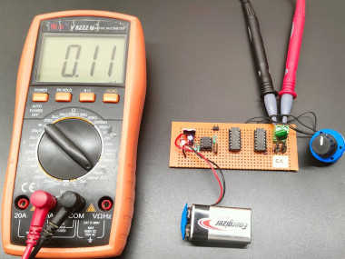
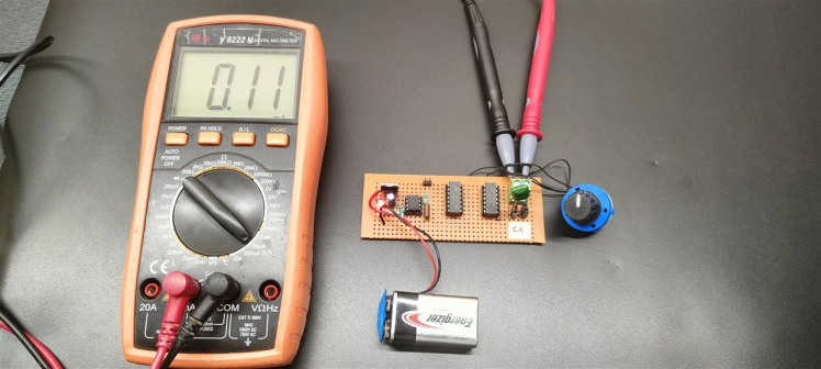
Here I have used a 555 timer IC along with a 74LS90 Decade counter to measure the capacitance using DC Ammeter.
555 Timer is used as a square wave generator in this circuit. During the High (1) square wave cycle, the capacitor (Cx) charges up to approximately 3.5 volts. During the Low(0) Cycle, the capacitor starts discharging.
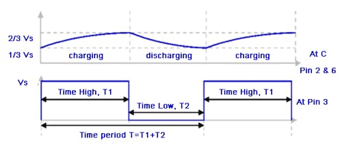
The 555 Timer clock frequency(f) will determine the discharge current through the ammeter. since Equation 1,
Q = C x VThen,fQ = fC x V......(Equation 1)
The Quantity fQ is the number of coulombs of the charge stored per second, and it is equal to the average current Flowing Through the capacitor(Cx)
fQ = dQ/Ddt = Ior,I = f C x V ........(Equation 2)
for example, assume an ammeter-sensitive scale is 100 microammeter, the clock frequency required to give a 0.1uf full-scale reading is found by rearranging equation 2,
f = i/ C x V
= 100uA/0.1uF x 3.4V
f = 294Hz
Working PrincipleThe NE555 is used as an astable multivibrator in this circuit, it generates the square wave at the frequency of 48KHz with a 66% duty cycle rate. I have chosen R1, R2 = 1K ohm and c = 0.01uF.
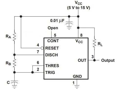
To find the frequency f = 1.44/(R1+2R2) X C
= 1.44(1K+2X1k) X 0.01u
= 48 KHz (Theoretical Value)
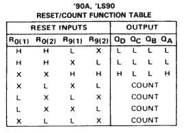
48KHz square wave signal is connected to the Decade counter Clock input, the 74LS90 Is activated to count function by enabling R0(1), R9(1) to Logic 0
A Rotary switch is used in this circuit to select the measuring scale range, This circuit can able to measure the Capacitor Value from 1nf - 10uF.
Circuit Diagram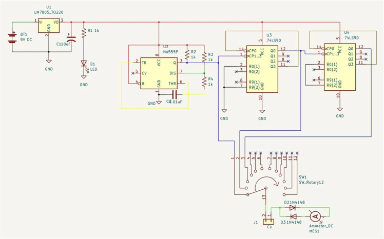
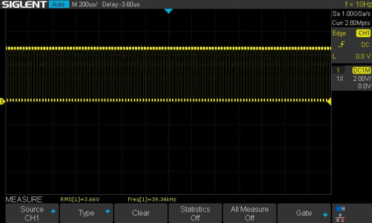
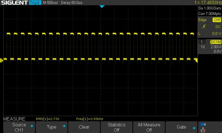
Output Waveform Of 555 Timer The theoretical Output frequency is 48KHz and the Practical Output Of the Circuit was 39kHz
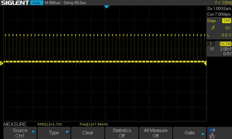
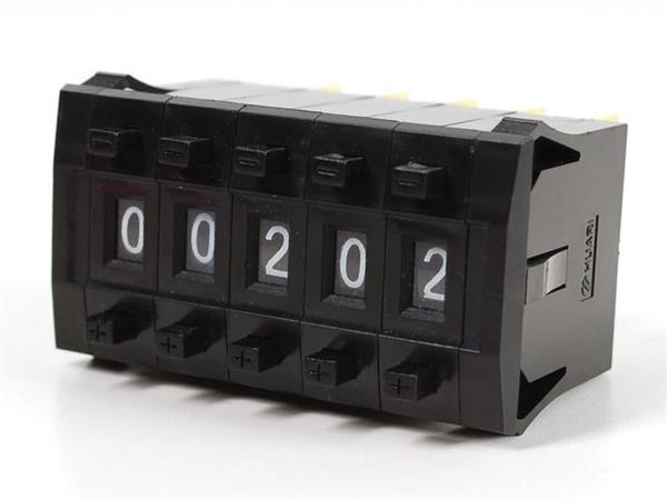
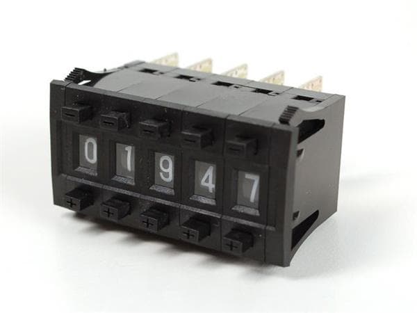
Output Of First Decade counter on the 12th pin of the IC (Output of First counter is then Fed to 2nd counter)
Schematics, diagrams and documents
Credits
Related products


Leave your feedback...