

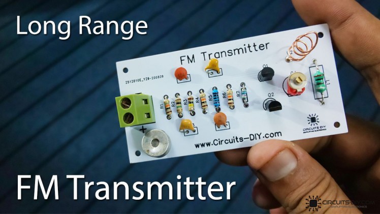
Build A Long Range Fm Transmitter Circuit

Made by CircuitsDIY
About the project
In this tutorial, we are going to make a long-range FM Transmitter Circuit using 2N3904 Transistors
Project info
Difficulty: Easy
Estimated time: 1 hour
License: GNU General Public License, version 3 or later (GPL3+)
Story
Details
What is a High Range FM Transmitter?An FM Transmitter is an electronic device that can air audio signals from a source on a selected range of frequencies. They are generally used to broadcast stationary audio from devices such as TV & computers, around a room. They are inexpensive & simple to design. So, in today's article, we will look into a step-by-step tutorial on how to make a High Range FM Transmitter circuit using some NPN transistors & a small no. of other components.
Whatever may be the schematic scope or design, every FM transmitter is based on the same three key stages: Audio pre-amplification, Modulation and, transmission. The first stage generally consists of amplifying & filtering an input audio signal. In the second stage, the input audio signal is modulated and a carrier signal is generated by a variable frequency oscillator circuit. In the last stage, the modulated audio signal is transmitted using an antenna between the FM frequency range of 88MHz to 108MHz.
JLCPCB is the foremost PCB prototype & manufacturing company in china, providing us with the best service we have ever experienced regarding (Quality, Price Service & Time). We strongly recommend ordering PCBs from JLCPCB, all you need to do is just download the Gerber file and upload it to the JLCPCB website after creating an account as mention in the video above, visit their website to look for more!.
Hardware ComponentsYou will need the following parts to build this project.
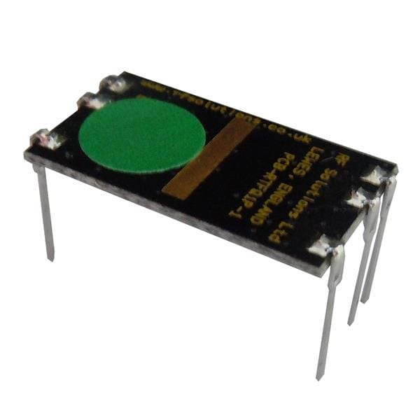
S.NoComponentValueQty1)FM Transmitter PCB-11)NPN Transistor2N390422)Condenser mic5mm13)Variable Capacitor40pF14)Inductor0.1uH15)Capacitor0.1uF, 0.01uF, 4.7pF36)Enameled copper wire18 AWG1.5ft7)Resistor1M, 100K, 10K, 1K, 100 Ohm78)Soldering Iron45W - 65W19)Soldering Wire with Flux-110)DC Battery9V111)Battery Clips-112)Jumper Wires-As per needCircuit Diagram
The working of this circuit is pretty simple, an input audio signal from a device such as a smartphone is taken through an electret mic. Here, a coupling capacitor of 0.1uF is used to block the DC component of the signal, allowing only AC to flow. This signal acts as a control signal to the base of the 2n3904 transistor (Q1).
Credits
Related products


Leave your feedback...