
Analog Input on Raspberry Pi with MCP3008
Made by talofer99
About the project
How to get analog input on Raspberry Pi using CircuitPython.
Project info
Difficulty: Easy
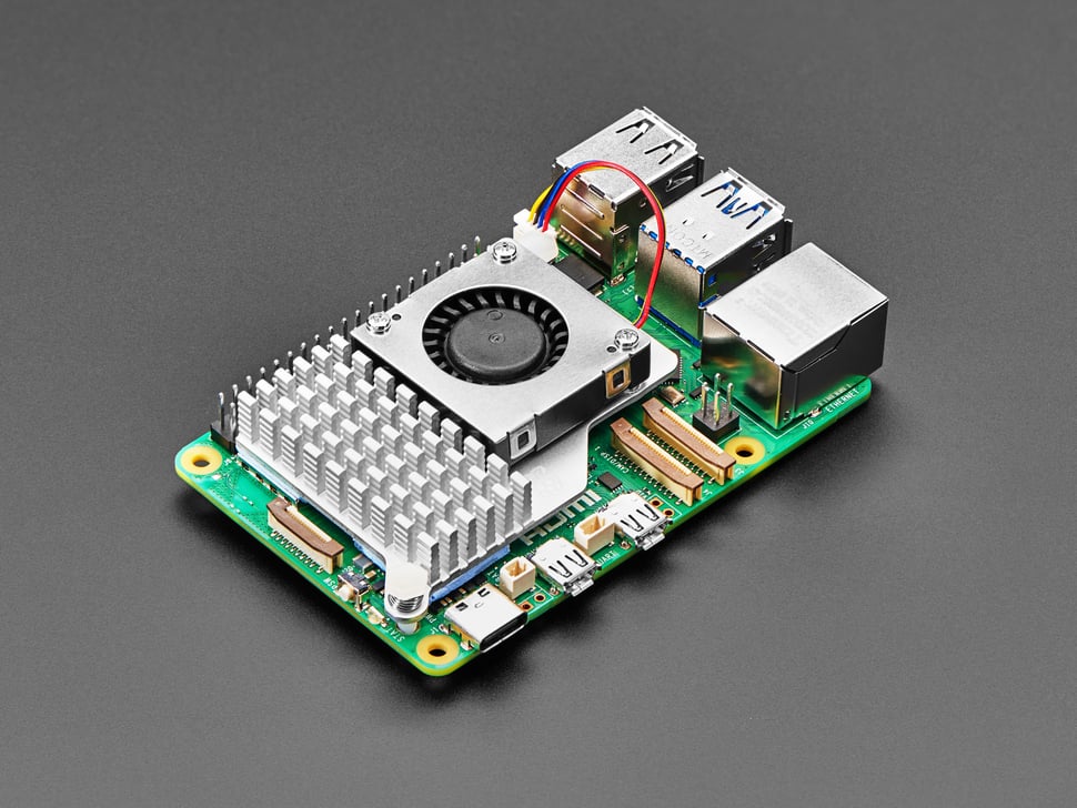
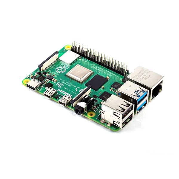
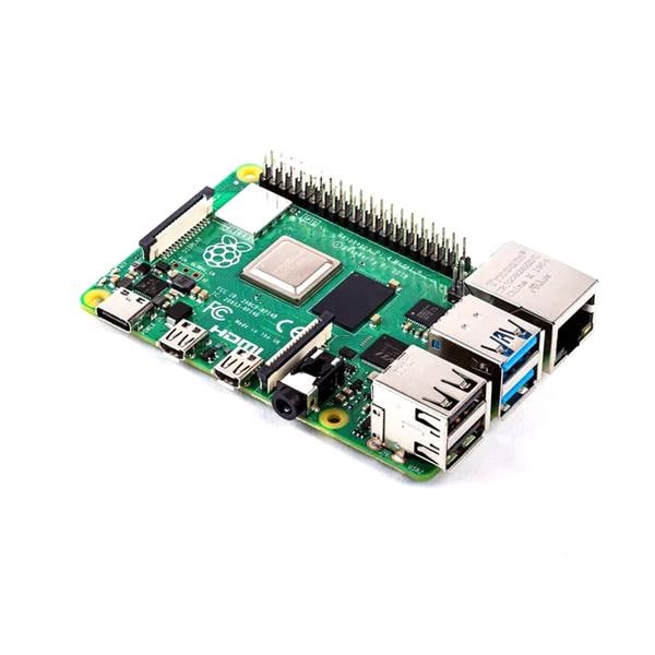
Platforms: Raspberry Pi
Estimated time: 1 hour
License: GNU General Public License, version 3 or later (GPL3+)
Items used in this project
Hardware components


Story
The lack of analog inputs on the rpi and how this can be solved with MCP3008 IC
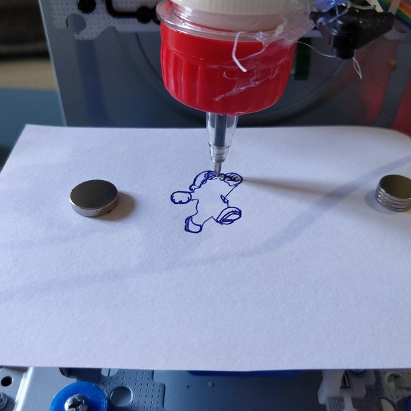
The MCP3008 is a 8-Channel 10-Bit Analog to Digital Converter IC with SPI interface.The first time I used this IC was when I worked on turning a x-box drum kit to a standalone electronic drums.
with the use of some python and well documented library from adafruit I was able to get it all running.
I did that project way back, Coming to get myself prepared for this tutorial, I noticed that adafruit released a newexample for the mcp3008 using circuit python.
https://learn.adafruit.com/mcp3008-spi-adc/python-circuitpythonCircuit
python, is a cross platform, variant of MicroPython. And since I did not get to use it yet, I decided to go ahead and use it for this tutorial.
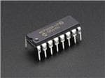
let’s first go over the IC pinout
https://cdn-shop.adafruit.com/datasheets/MCP3008.pdf
On the left side of the IC we got the 8 analog input pins marked CH0 to CH7.ON the right side We got all the SPI pins: CS, DIN, DOUT and CLK.And we got the Vdd and DGND for the IC power and the Vref and AGND for analog reference. In this
clear drawing you can see the way It should be connected to rpi.https://learn.adafruit.com/assets/64125
There are few things to setup in order to use circuit-python First if you have not done that yet, is to enable SPI and I2C on the raspberry pi settings.I’m connected using SSH, but this can be on the rpi itself.
open the settings by typing sudo raspi-config and goto Interfacing Options setting both the SPI and I2C to enabled.
It is always agreat idea to updating your rpi OS before installing things.So run following
sudo apt-getupdate
sudo apt-getupgrade
sudo pip3install --upgrade setuptools
Install support for the GPIO in python sudo pip3 install RPI.GPIOinstall CircutePython to python 3 pip3 install adafruit-blinkaand the reason weare all here install the library for the MCP3008 https://github.com/adafruit/Adafruit_CircuitPython_MCP3xxx
sudo pip3 install adafruit-circuitpython-mcp3xxx
and last thing – I promise – is the bundle that will bring the busio library with itpip3 install adafruit-circuitpython-lis3dh
and now we are ready to rock and roll, let’s take the first example and run it and as you can see we got a result back, my Potentiometer is set roughly in the middle, so value of 1.7 is just about half of 3.3
Let’s review the code.We first import the needed libraries.The spi bus is declared with the right GPIO
We define the CS pin that is needed for the spi as well And then we create the MCP object.
From that object we can get the analog read value of P0 which is the CH0 on the IC. and last we print the channel value and voltage – which is a calculated value. Note that the value go way past the 10bit limit which is 1023.
The reason for that is that adafruit has mapped the value to meet her other libraries output of 16bit – so don’t let that surprise you.
Schematics, diagrams and documents
Code
Credits
Related products


Leave your feedback...