
2-axis Multi-fab Machine

Made by Rashidt
About the project
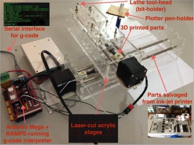
Build a 2-axis machine with changeable tool-heads (plotter + lathe-tool-bit in the first iteration)
Project info
Items used in this project
Hardware components


Software apps and online services
Story
Highlights
- Started building a lathe, moved to building a 2-axis machine with changeable tool-heads (plotter + lathe-tool-bit in the first iteration)
- Salvaged inkjet printer parts from local scrapyard
- Some parts are 3D printed
- Custom-built acrylic stages
- RAMPS controller running a g-code interpreter available over serial interface
Material Required
We did not have the MTM stages or the Gestalt boards in the lab, so we had to make or salvage all the parts.
We needed the following material:
- Lathe
- A headstock with a chuck to hold the workpiece
- A motor to power the spindle
- And optionally a tail-stock to support the workpiece
- X & Y axis stages with
- guide rails
- stepper motor
- lead screw
- coupler
- tool-holder
- RAMPS board with Pololu stepper driver
We decided to 3D print the lathe parts, some in PLA using the Ultimaker and others, like the coupler, in ABS using the Stratasys printer.
The X, Y stages would be designed and laser-cut out of acrylic.
For guide rails, we would salvage parts from a scrapyard.
We had stepper motors in the lab.
Pooling Parts
we set a rule of not buying any mechanical components for the machine, instead salvage or make it our self. We are strictly adhering to the rule that "we will be making or salvaging whatever we could, we will do the best we can".
Scrap Hunt
We were hopping to get Motors including stepper motors, threaded rods, smooth rods, timing belts, other useful mechanical components like gears, springs, screws. We could also get many useful electronics components too, like power-bricks (power bricks of the printers), positions sensors, switches, connectors etc.
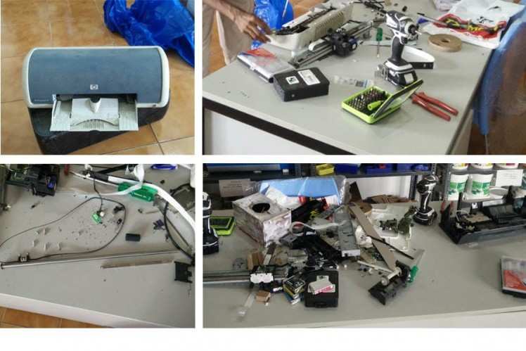
In summary, this is what we got.
- 9 X DC Motors.
- 1 X Stepper motors.
- 3 X 8mm, 40cm smooth rods.
- 3 X 8mm, 30cm smooth rods with a gear like tooths at 1/3rd the length.
- 5 X 6mm smooth rods of various lengths.
- 5 X long timing belts and few shorter ones.
- 2 X Possibly working 230V AC to 19V DC power bricks.
- Many optical positions sensors and endstops.
- Many screws and springs and gears of various types and sizes.
We also got smooth rods for the guide rails. But we couldn't get any threaded rods, and we need it for the machines. There are again multiple options, could use standard threaded rods that are used for fastening, we could use long bolts, or we could use the special high quality threaded rods made for actuation, like the ones used in Ultimaker's Z-axis. There was one vendor how refused to give anything short of 3m. We didn't require long threaded rods as this is a experimental build, need only small axes. We could use the long bolts instead, and we decided to do so.
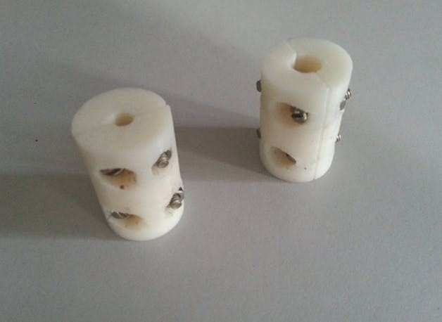
3D-Printing Lathe Parts
we need to work on to design a coupler for the stepper motor to the treaded rod coupler, 5 mm to X mm coupler with parametric design.
This was the thingiverse design we have taken into consideration for the coupler. We took a test print in Ultimaker, and found out that the piece cannot withstand much strain. So, we took print in ABS plastic using dimensions.
X-Y Stages
We need to design the X and Y stages using the materials available at the lab and the salvaged parts.
So, we decided to make something simple using the smooth rods we have and the two long bolts
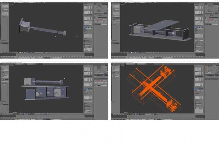
I decided to use the blender for design model of machine
1 / 2

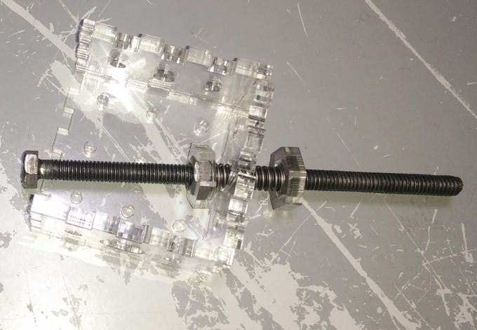
Design and Final Box assembly
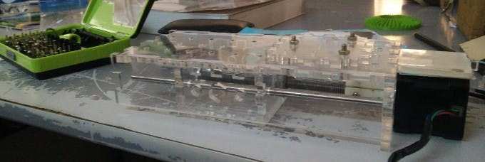
The final box assembly, Notice the use of two nuts on the bolts, and a spring in between the nuts. This spring will keep the nuts under load and backlash should be less. Also, the two nuts will provide extra stability. The nuts are fixed using the hexagonal acrylic pieces, they will be glued to the box two lock the positions of the nuts. I have only done this for X-axis, so that I can compare the results.
The Y-stage ready to be mounted on the X-box/carriage. Three m4 bolts have been used to fix the mounting plate to the bottom of the Y-stage. This will be fitted (press fit) on the X-carriage. The motors too are press-fitted and also supported by a piece of acrylic base-plate glued to the main assembly.
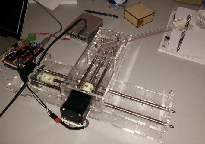
The complete assembly with a 'makeshift' pen plotter and RAMPS 1.4 controller board.
Automation
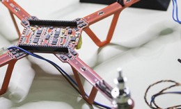
We did not have Gestalt boards or the MTM stages in the lab. Sibu tried to fabricate Gestalt and Fabnet boards. However this was taking up too much time and we decided to use RAMPS (RepRap Arduino Mega Pololu Shield).
We might replace this with a stateless Fabnet-based approach later.
The first step was to check if RAMPS was working fine and could move a single stepper motor.
We hooked up the boards and motor and used RAMPS test code to test it.
Here is the modified code we used:
#define X_STEP_PIN 54
#define X_DIR_PIN          55
#define X_ENABLE_PIN       38
#define LED_PIN            13
void setup() {
 pinMode(LED_PIN  , OUTPUT);
 pinMode(X_STEP_PIN  , OUTPUT);
 pinMode(X_DIR_PIN    , OUTPUT);
 pinMode(X_ENABLE_PIN    , OUTPUT);
 digitalWrite(X_ENABLE_PIN    , LOW);
}
void loop () {
 if (millis() %1000 <500)
   digitalWrite(LED_PIN, HIGH);
 else
   digitalWrite(LED_PIN, LOW);
 int i;
 digitalWrite(X_DIR_PIN    , HIGH);
 for (i = 0; i < 5000; i++) {
   digitalWrite(X_STEP_PIN    , HIGH);
   delay(1);
   digitalWrite(X_STEP_PIN    , LOW);
 }
 digitalWrite(X_DIR_PIN    , LOW);
 for (i = 0; i < 5000; i++) {
   digitalWrite(X_STEP_PIN    , HIGH);
   delay(1);
   digitalWrite(X_STEP_PIN    , LOW);
 }
}
Next step was to figure out a way to control the machine with an instruction set rather than hardcoded stepper movements.
For this we decided to implement a simple G-code interpreter, which would run on RAMPS and communicate with a host using a serial interface.
We found a very useful implementation of a 2-axis G-code interpreter here.
The full source is available here:
In the video below you can see the interaction being demoed:
- connect to the serial port using screen
- the gcode interpreter on RAMPS outputs an intro message and a help menu of supported G-code commands
- enter G-code command: "G00 X800". This rotates the shaft clockwise 90 degrees (each step is 1.8 degrees and we are using 16 microsteps per step).
- enter G-code command: "G00 X0". This rotates the shaft anti-clockwise 90 degrees.
The next step was to write a simple way to input g-code commands. We used pyserial for this.
import serial
import fileinput
def consumeLines():
   while True:
       l = ser.readline().strip()
       print ">>> " + l
       if l == ">": # wait for the device to be ready for the next command
           break
ser = serial.Serial('/dev/cu.usbmodem1411', baudrate=9600, timeout=None) # block forever on reads
ser.isOpen()
consumeLines()
for cmd in fileinput.input():
   print "sending cmd: " + cmd.strip()
   ser.write(cmd)
   consumeLines()
ser.close()
Now we can invoke it like this:
$ python serialsend.py square.gcode
And square.gcode can contain raw gcode commands like this:
G00 X10000
G00 Y10000
G00 X0
G00 Y0
Possible Improvements
- Use mods with g-code generation to get a working UI
- Alternatively try Makelangelo UI for the same
Credits
Related products


Leave your feedback...