
Made by ElectromakerKits / 3D Printing / Lights / Retro Tech / Wearables
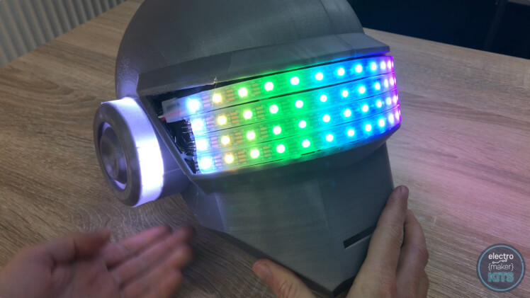
Inspired by the classic Daft Punk 'Thomas' helmet. Light up the room and be the envy of all your friends with this amazing Arduino powered disco helmet! You will need access to a 3D printer and a soldering iron to complete this project.
Difficulty: Moderate
Platforms: Adafruit, Arduino, noads
Estimated time: 2 days
License: GNU General Public License, version 3 or later (GPL3+)
|
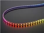
Adafruit NeoPixel Digital RGBW LED Strip - Black PCB 60 LED/m 1m | x 1 |
|
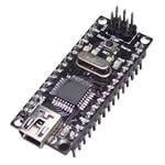
DFRduino Nano | x 1 |
|
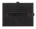
Breadboard Mini Self Adhesive Black | x 1 |
|
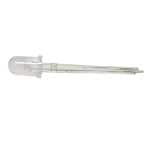
White Diffused 680mcd, 20mA | x 6 |
|
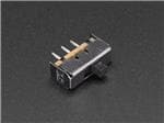
Breadboard Friendly SPDT Slide Switch | x 1 |
|
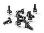
Tactile Switch Buttons 10 pack | x 1 |

|
USB Cable A/MicroB - 3ft | x 1 |
|
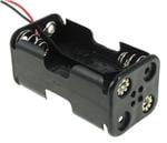
4XAA 6" LEADS BLK | x 1 |
|
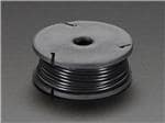
Stranded-Core Wire Spool - 25ft - 22AWG - Black | x 1 |
|
Stranded-Core Wire Spool - 25ft - 22AWG - Blue | x 1 |
|
Stranded-Core Wire Spool - 25ft - 22AWG - White | x 1 |
View all
|
|
Arduino IDE |

|
3D Printer | x 1 |
|
|
Soldering Iron | x 1 |
|
|
Glue gun (or you could use super glue) | x 1 |
We love Daft Punk Helmet builds. That's why we simplified and remixed Adafruit's design to make it accessible for makers with smaller print beds. The inspiration came from this project:
https://learn.adafruit.com/3d-printed-daft-punk-helmet-with-bluetooth/3d-printing
There are eleven 3D printed parts to this project. I printed all my pieces with PLA filament. You can use whichever colour you prefer, I've chosen a slightly metallic silver.
Some of the prints are quite large and will take some time to print. I'll explain how I printed each of mine as shown in the video as well as provide tips for any possible common faults:
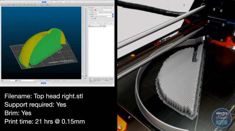
Layer height: 0.15mm (for detail on the curves)
Supports: Yes
Brim: Yes (this will help with adhesion)
Orientation on the print bed: On its side
Print time: about 21 hours
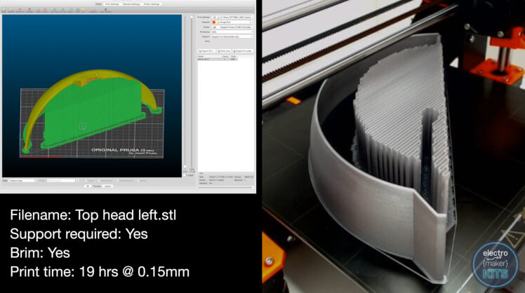
Layer height: 0.15mm (again for detail on the curves)
Supports: Yes
Brim: Yes (this will help with adhesion)
Orientation on the print bed: On its side
Print time: about 19 hours
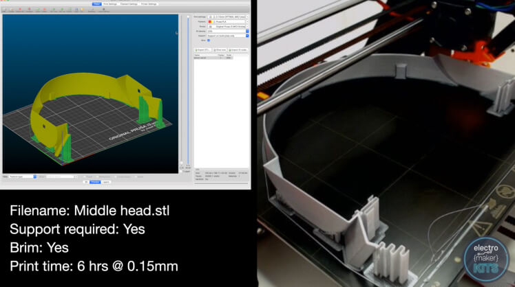
Layer height: 0.15mm (for detail on the curves)
Supports: Yes
Brim: Yes (this will help with adhesion)
Orientation on the print bed: Upside down - this is so the overhangs will be inside the helmet. Overhangs can sometimes be printed at a lower quality so we'll keep this hidden on the inside of the finished model.
Print time: about 6 hours
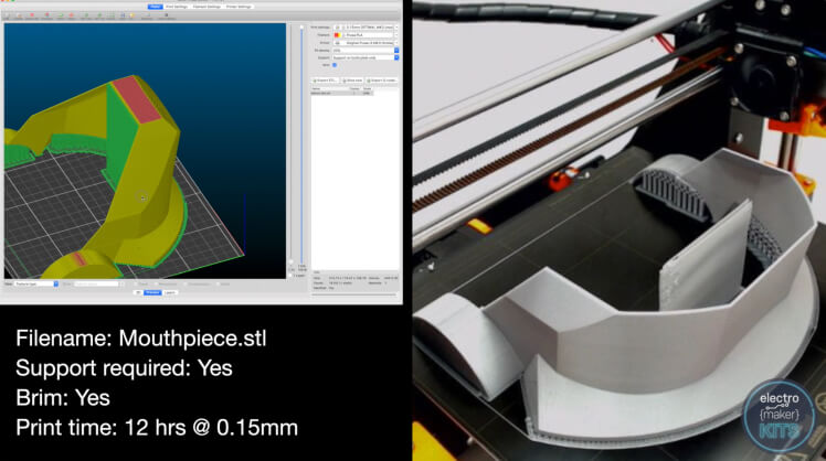
Layer height: 0.15mm (for detail on the curves)
Supports: Yes
Brim: Yes (this will help with adhesion)
Orientation on the print bed: Upside down -this gives more area for contact with the print bed.
Print time: about 12 hours
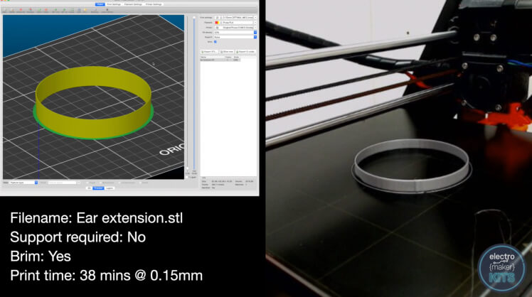
Layer height: I printed mine at 0.15mm but as all the walls are vertical you could print this at 0.2 or 0.3mm with little drop in quality.
Supports: Not required
Brim: Yes (this will help with adhesion)
Orientation on the print bed: Flat on the bed
Print time: about 38 minutes
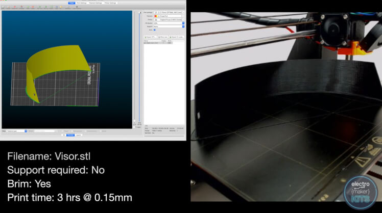
Layer height: 0.15mm
Supports: Not required
Brim: Yes (this will help with adhesion)
Orientation on the print bed: Upside down as this gives more contact with the print bed
Print time: about 3 hours
I printed this part in black to as to blend in with the black backing on the LED strips used.
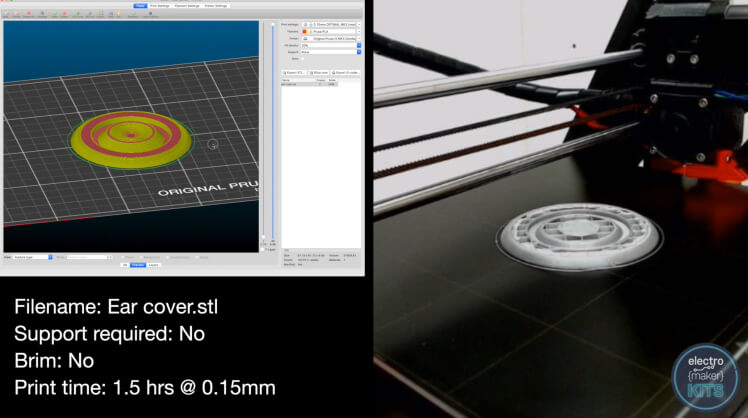
Layer height: I printed mine at 0.15mm
Supports: Not required
Brim: No
Orientation on the print bed: Flat on the bed
Print time: about 1.5 hours each
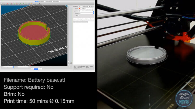
Layer height: I printed mine at 0.15mm but as all the walls are vertical you could print this at 0.2 or 0.3mm with little drop in quality.
Supports: Not required
Brim: No
Orientation on the print bed: Flat on the bed
Print time: about 50 minutes
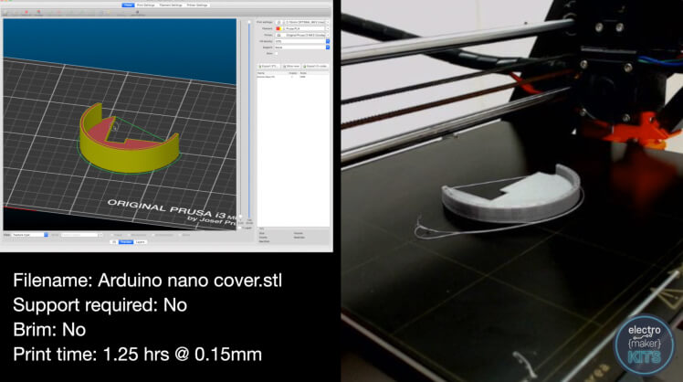
Layer height: I printed mine at 0.15mm but as all the walls are vertical you could print this at 0.2 or 0.3mm with little drop in quality.
Supports: Not required
Brim: No
Orientation on the print bed: Flat on the bed
Print time: about 85 minutes
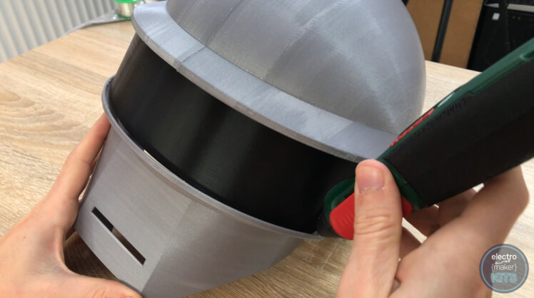
I'm going to use super glue to join my pieces together because it is quick to dry and has a strong hold. Be careful not to glue yourself to the model - this is easily done if you don't pay close attention!
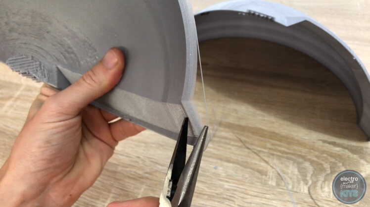
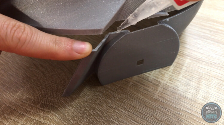
Before we take the lid off the glue we need to remove the support material from our prints. We'll be glueing the two top parts of the helmet together first so this is great place to start with support removal.
Once removed we can apply dabs of super glue along where the two parts join. Apply the super glue to only one side and then carefully press them together.
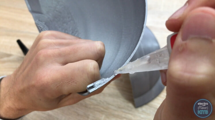

To make this step easier to align I only glued halfway along the joint before holding the two half together. Once this had set I then added glue to the rest of the joint.

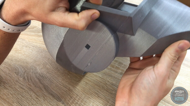
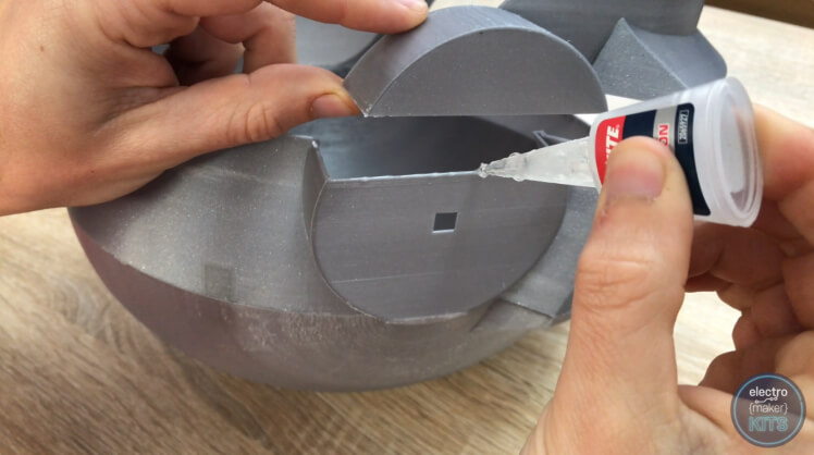
Now we can take the middle section of the helmet, carefully remove the brims and support material from the print and then glue this to the top two pieces we have just been working on.
Again, apply some dabs of glue along one half of the total length we need to join. Bring the two parts together and hold in position as it dries. Now apply glue to the rest of the join and repeat.
If your parts have not printed out exactly as they should then I would recommend ensuring that the front end of the prints meet up as intended and that any 'miss-fit' is hidden at the back of the helmet. The back of the model is rarely going to be seen and, if you wanted to repair any mismatch, it will be easier at the back than amongst the various contours at the front.
Now turning our attention to the mouthpiece, remove the support structures and brim and apply glue along the area to be joined on one side. We do not need to apply glue along the entire length of this piece - only the area near the two ears actually makes contact with the rest of the print.
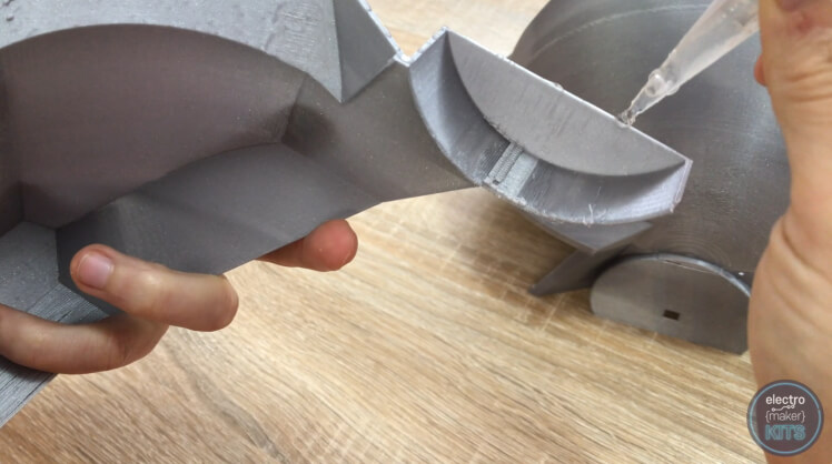
Repeat the same steps for the other side taking care to align the prints well.
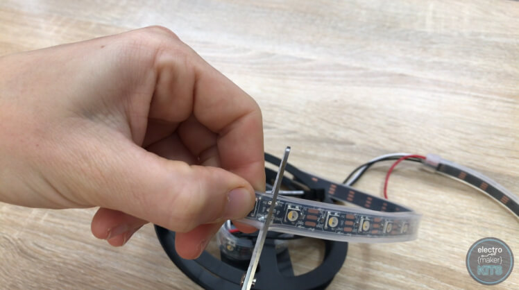
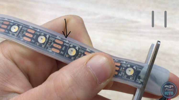
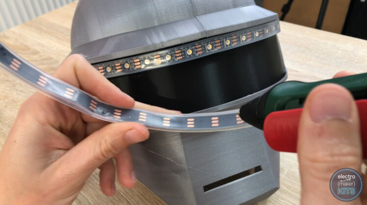
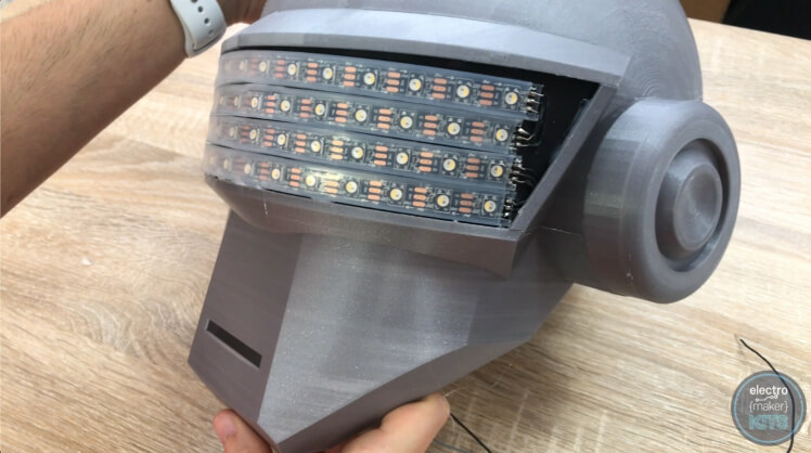
Unravel the length of Neopixels from the reel they arrived on. We need to cut them up into four equal lengths of 15 LEDs each. After you have counted 15 LEDs and are ready to cut through the strip (ordinary scissors will be adequate) ensure you cut through the centre of the copper contact pads.
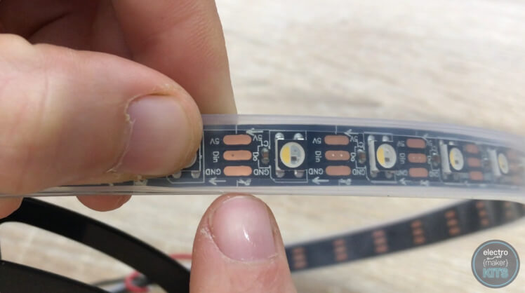
There are markings on the strip itself that show you where to cut. You may find that where you need to cut there is solder across the copper pads - don't worry just cut straight through the solder as you would with the copper pads.
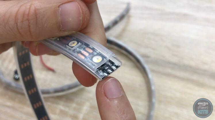
To make soldering to these strips much easier later on, we can remove some of the plastic protective sheathing from above the three solder points using our scissors. Do this to both ends of the 15 LED long strips which have no wires attached to one end.
 Now we are left with two strips which each have some wires left on them at one end.
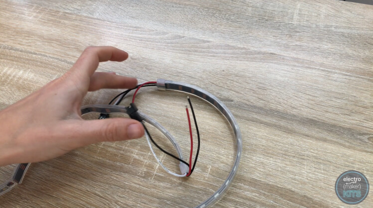
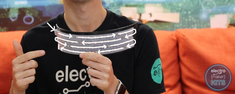
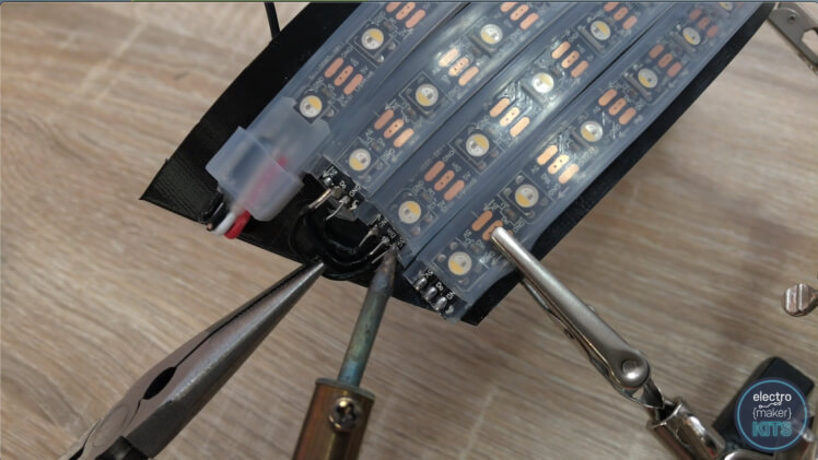
Locate the strip which has the arrows showing the direction of data flow on it (the white arrows on the flexible tape) pointing towards the end with wires already attached. Remove the wires entirely from this strip by cutting through a row of contact pads again - look carefully as it may be partly concealed by glue.
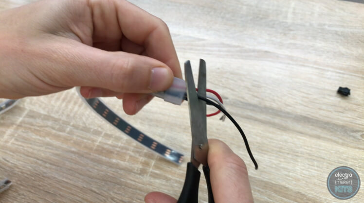
On the other strip, we can remove the plastic connector from the end of the wires and then also trim the black wire which was going to this plug at the base of the LEDs.
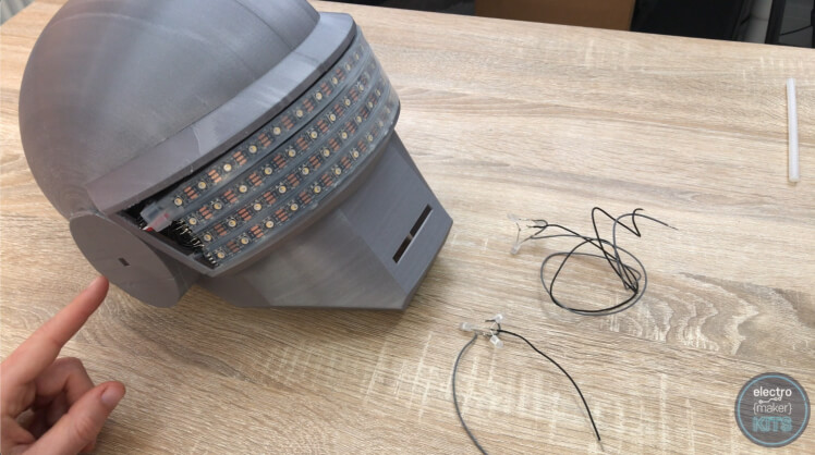
Remove the brim and tidy up your 3D printed visor.

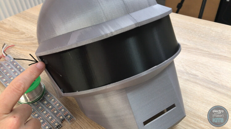
We will now temporarily fit this inside the helmet to help us better align the LEDs. Fit the printed part inside the visor from the inside of the helmet and use four small dabs of hot melt glue in the corners. Don't use too much glue as we will be removing it again shortly to making soldering easier.
When installing the LED's there are several things you need to be aware of.
Once you have finished glueing the strips in place you can tuck the three wires through their hole in the top left of the visor.
We can push the visor with the LEDs on back out of the mask. This will make soldering easier.
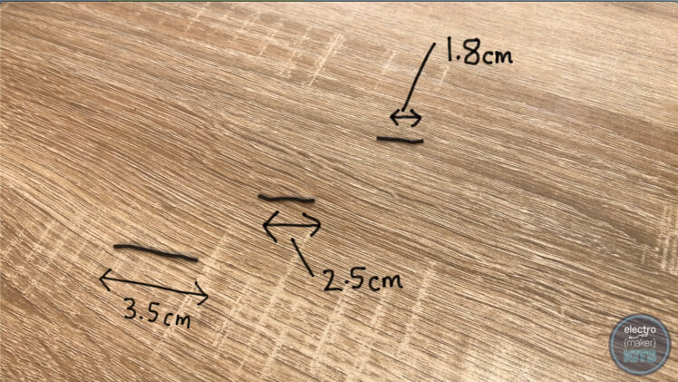
You will need to prepare the following lengths of wire:
We included plenty of black wire in your kit and I recommend you use this to help hide the wiring against the black visor and black backing on the LED strip.
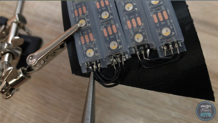
You will need to strip the ends of each wire and then bend them into a 'U' shape.
Now you need to solder them at the ends of the LED's where our strips double back on themselves. The contacts are labelled as either '5V', 'DIN' or 'GND'. We need to solder like to like using the 'U" shaped bits of wire.

Next up we will extend the three wires coming from the LED strip. Your kit contains black, grey and white wires.
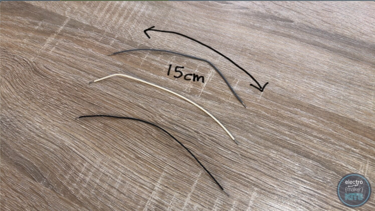
Prepare a 15cm length of each and then solder:

Once the soldering is complete, wrap some insulation tape around each joint to prevent the circuit from shortening later.
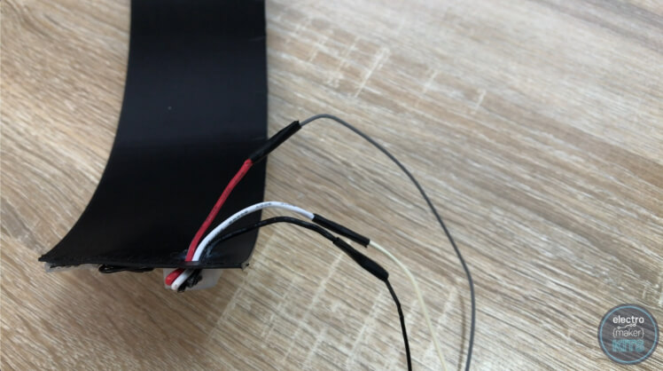
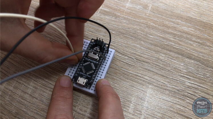
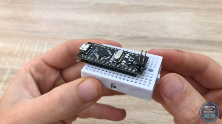
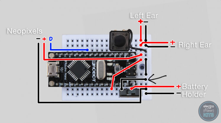
It would be a good idea now to test our LEDs to verify that the soldering we have done is working before we fix the visor in place back inside the helmet. To do this, place the Arduino Nano into the breadboard. We then need to connect the black wire from the LEDs to a ground connection on the Arduino, the grey (formerly red) wire to 5V on the Arduino and finally the white wire to D6.
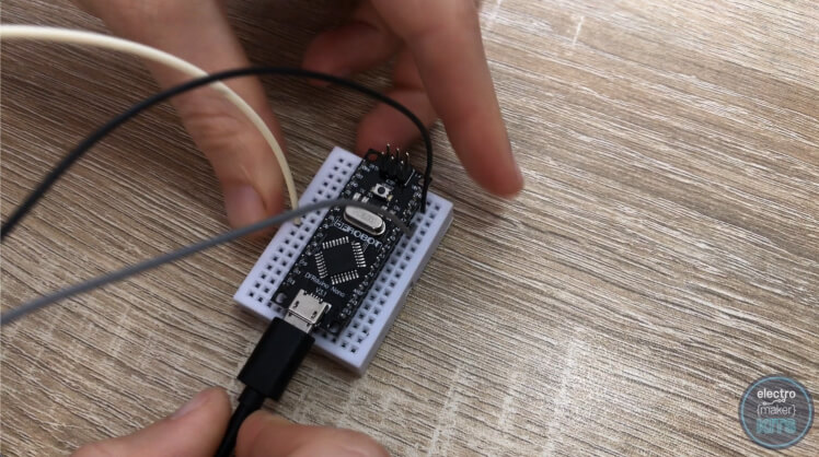
Now connect your Arduino to your computer using the included USB lead and open the Arduino IDE. If you have not yet installed this you can find the free download and instruction here: https://www.arduino.cc/en/main/software
We need to install a couple of libraries. The first one is Adafruit's Neopixel library.
To do this, in the Arduino IDE go to:
Sketch >> Include library >> Manage Libraries

From here search for 'Neopixel'. Look for Adafruit Neopixel by Adafruit and install the latest version.
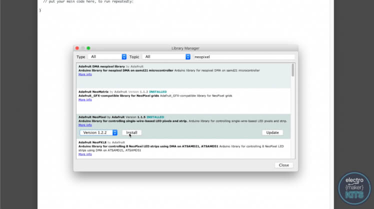
You then close the windows after the install is complete.
The second library you need it the WS2812FX library. This can be downloaded from https://github.com/kitesurfer1404/WS2812FX

You can download a zip of the repository by clicking 'Clone or Download' and then 'Download ZIP'

Extract the downloaded file into your Arduino IDEs Library folder.
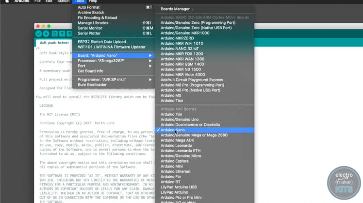
The last bit of code you will need is the one written for this project. You can find it at the end of this article. Open it in the Arduino IDE. To be able to upload the code successfully ensure you have the board type 'Arduino Nano' selected.
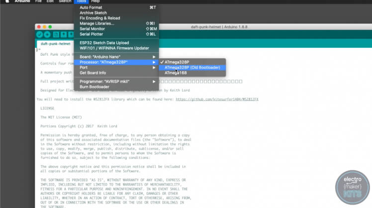
and the processor 'ATmega328P (Old Bootloader)' selected from the tools menu.
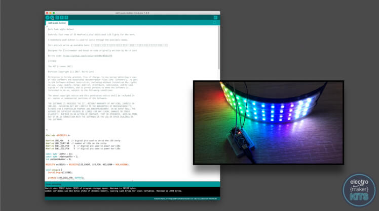
Now press the upload button in the Arduino IDE (top left) and if everything has been connected to together properly you should see the LEDs spring into life!
Now we know the LEDs are working as expected we can glue the visor back inside of the helmet. This time use more glue as we want it to be a more permanent hold.
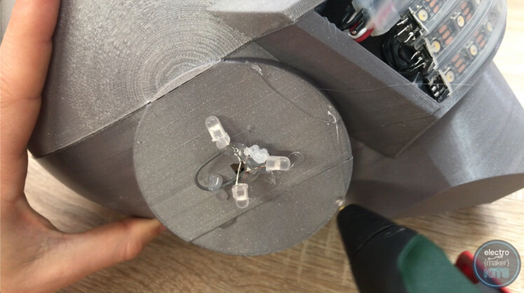
You will also find some diffused white LEDs in your kit, these are for adding into the ears so that they light up when the power to the Arduino is on. If you do not want your ears to light up you can skip this step, otherwise read on.
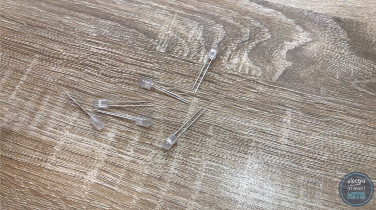
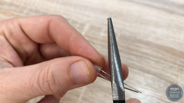
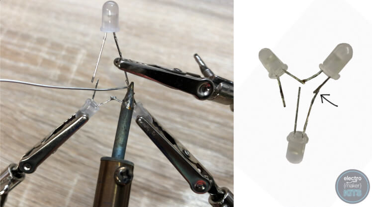
Trim the legs on two of the LEDs to about half of their original length. Before you cut them though, you'll see that one leg is shorter than the other. Ensure this leg is still the shortest after you have cut them by cutting them at an angle or individually.
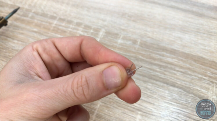
Carefully bend the legs outwards slightly on both the LEDs.
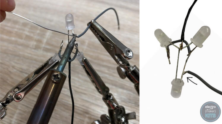
Solder the two negative (shortest) legs together as shown below.
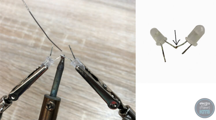
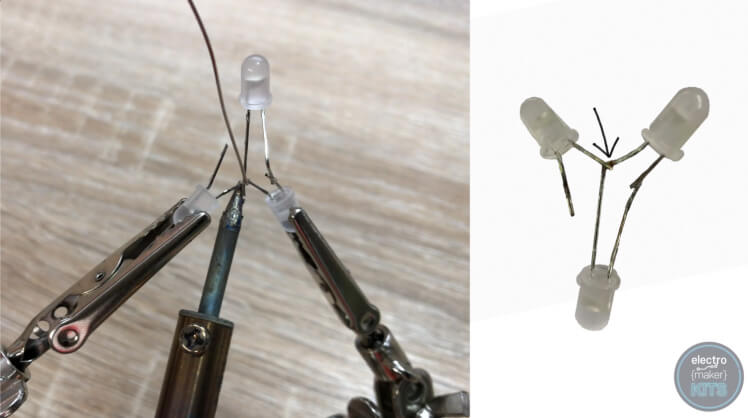
Add a third untrimmed LED by soldering its longest positive leg to one of the long positive legs on the other two trimmed LEDs.
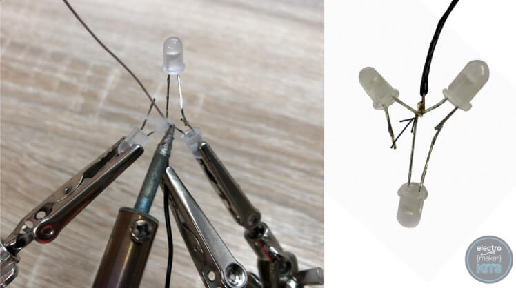
The negative leg of the untrimmed LED can then be soldered to the two other negative legs we soldered together earlier. You may need to bend one or more of the legs already soldered to accommodate this.
Prepare a 10cm length of wire (I used black) and also solder this to the negative legs.
Add a short length of wire to the unconnected positive leg or the trimmed LED to join it to the two other positive legs which are already soldered together.
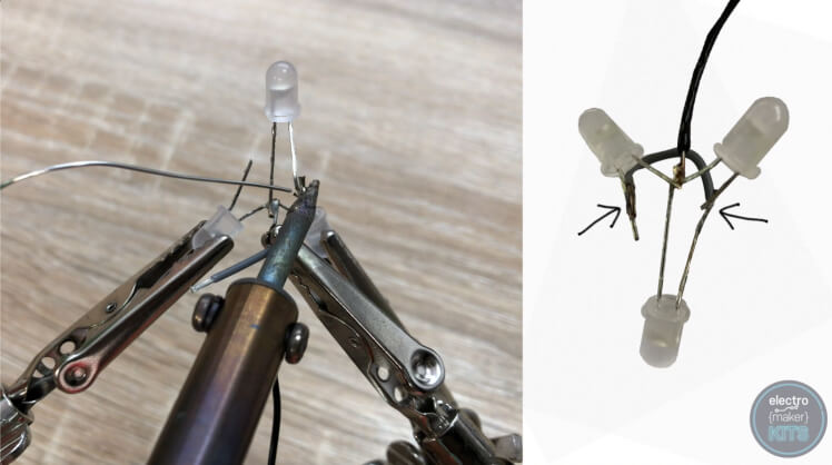
We now need to solder one more 10cm length of wire (I sued grey if you want to follow along) to one of the positive LED legs.
These can be checked quickly by connecting the grey wire to 3.3V on the Arduino via the breadboard it's on, and the black wire to GND (ground). Connect the Arduino Nano to a powered USB port and the LEDs should instantly light up.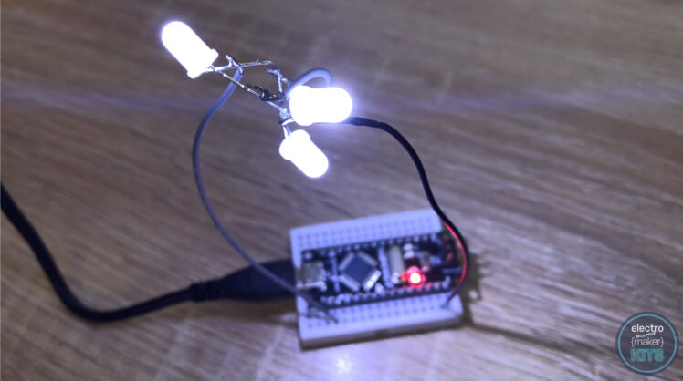
This one ear's worth of LEDs complete. Repeat the same steps again to prepare the other ears LEDs but this time instead of adding 10cm lengths of wire, use 55cm lengths.
The LEDs with the 10cm lengths of wire attached are intended for the right ear (as seen as though you were wearing the helmet) as this ear will be closest to the Arduino Nano. The other LED assembly is for the left ear.
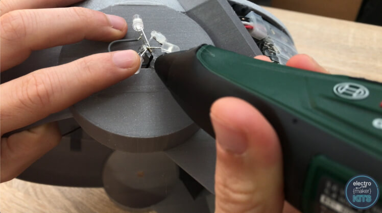
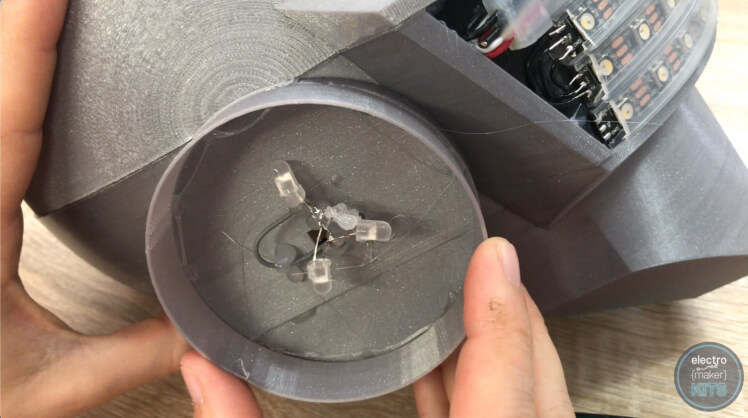
Thread the wires for the LEDs through the hole on the side, then use plenty of glue to hold the LEDs in place as close to the center of the ear as you can. It's also beneficial to keep them pointing away from each other in a triangular fashion if you can so that they can light the ear up uniformly. Don't worry about using to much glue as this area of the ear will not be visible later.
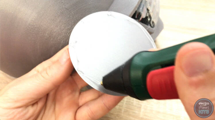
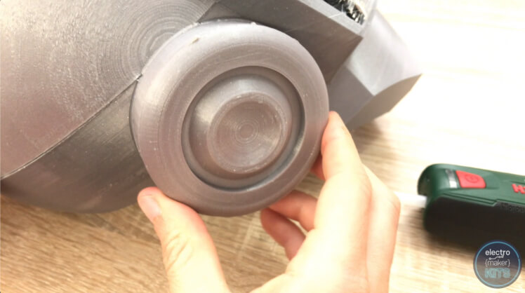
Now take one of the outer ear prints, apply some glue to the edge of the ear on the mask and carefully fix the two together.
We'll now apply some glue to the edge of the ear cover and then install this into place completing the first ear.
Again, repeat the same steps above for the opposite ear. The only difference is that this time you'll be using the set with 55cm wires attached.
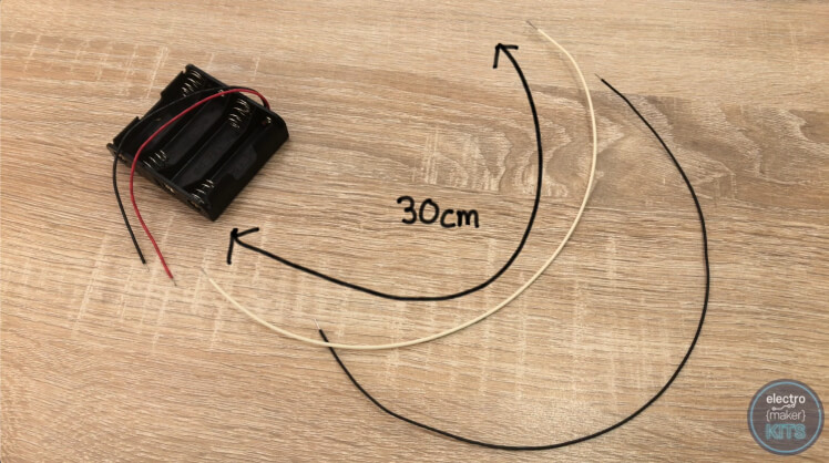
Extend the two wires on the battery pack with two 30cm lengths of wire. I soldered a black wire to the black lead on the battery pack and white wire to the red wire coming from the battery pack.
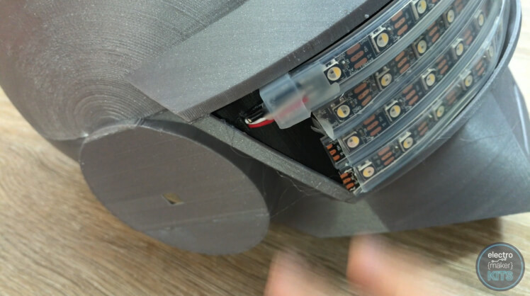
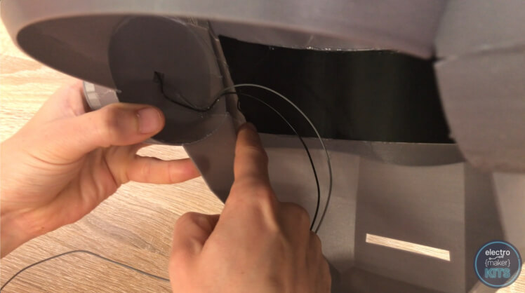
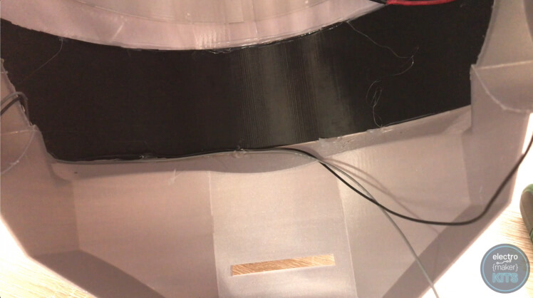
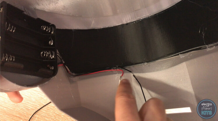
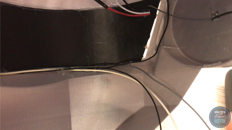
We will now start to tidy up the bundle of wires collecting inside the helmet. First, apply some glue to the inside of the ear with the longest wires and fix these in place so that they hug the print as they enter from the ear and head towards the visor.
Then bend and glue the wires into the bottom of the visor and then sideways along the bottom until they reach the other ear. Take a look at the photos following if you're not sure:
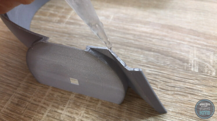
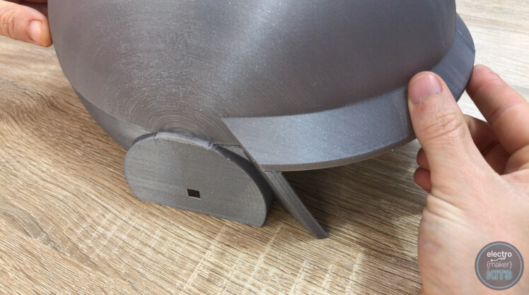
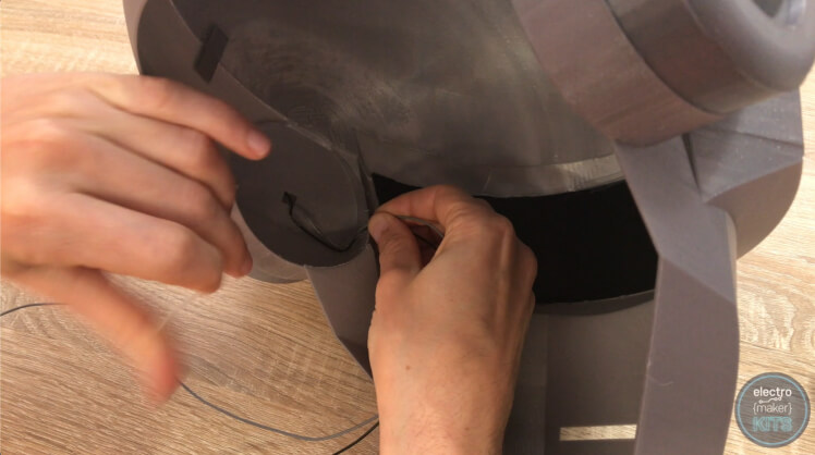
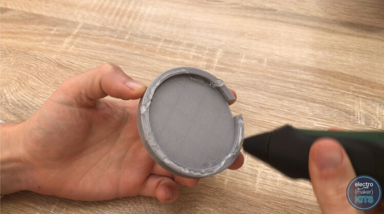
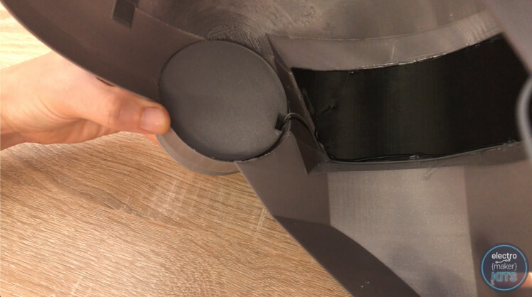
Now apply plenty of glue to the bottom edges of the 3D printed battery base. This is to be fitted over the inside of the left ear covering where the wires enter the helmet. The notch in the battery base is to align up with the wires we just glued so that it is not pinched or damaged in any way.
Apply glue to the back of the battery holder and fix this to the battery base we just fitted. Ensure that the end where the wires leave the battery holder is aligned with the wire from the LEDs as we will then glue the battery wires along the same route as the LED wires.
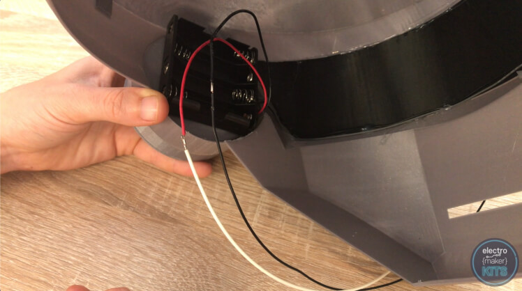
When you get to the soldered joints of the battery wires add some insulation tape to them if you have not already. When you get near the ear you can stop fixing the wire into place.
I'll now guide you through connecting everything to the Arduino via the breadboard. When we extended wires or added wires to LEDs earlier in the project I suggested you used lengths which will be more than long enough to reach the breadboard. As you connect items to the breadfor please feel free to shorten them if you find you have an excess amount.
You'll need to remove the Arduino from the breadboard if you have already added so that we remove some of its legs. The once which need removing are labelled below:
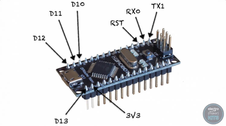

You can use some snip to trim them away. This is so that it can fit it onto the breadboard where we need it to be.
You will also need to remove this leg from the momentary switch:
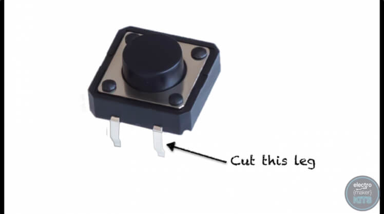

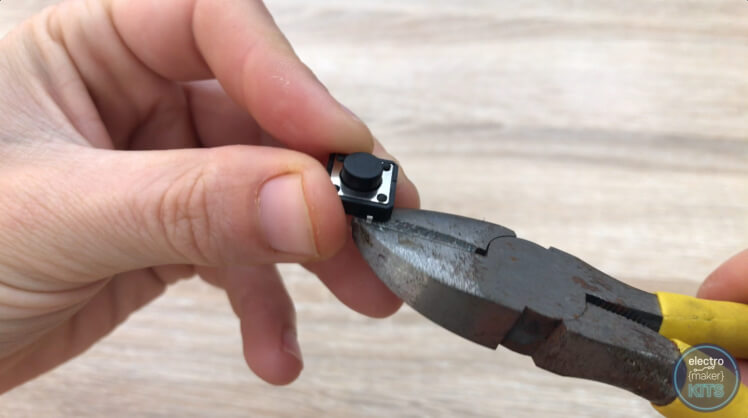
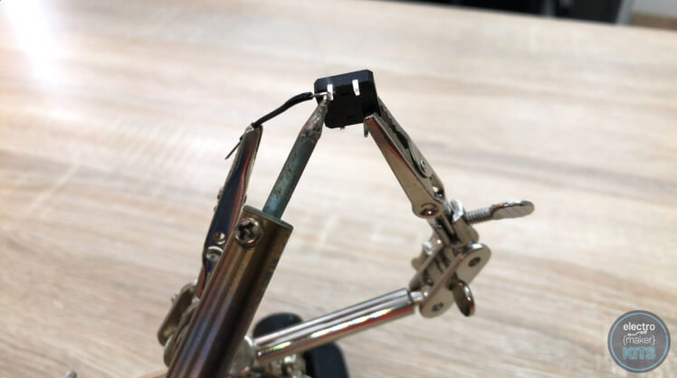
Solder a short 2.5cm piece of wire to the foot opposite the one you just removed.
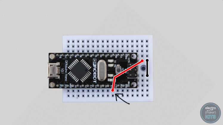
From now on when I talk about the position of the holes on the breadboard I will be assuming that you are looking at it from the top down with the USB port on the left as shown below. I will also count the position of the holes starting from the bottom right-most position on the breadboard. To position your Arduino as I have mine, ensure that the Arduinos VIN pin is three holes up and five in from the right - everything else should then fall into place.
Insert a new small length of wire to bridge the gap between the two halves of the breadboard on the far right-hand side.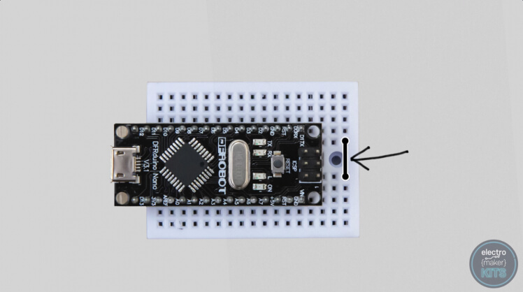 With a slightly longer wire connect the Arduinos 5V to the second column in at the top of the breadboard.
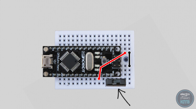
The sliding switch is then positioned so that its three legs go through the third, fourth and fifth holes along the bottom of the breadboard.
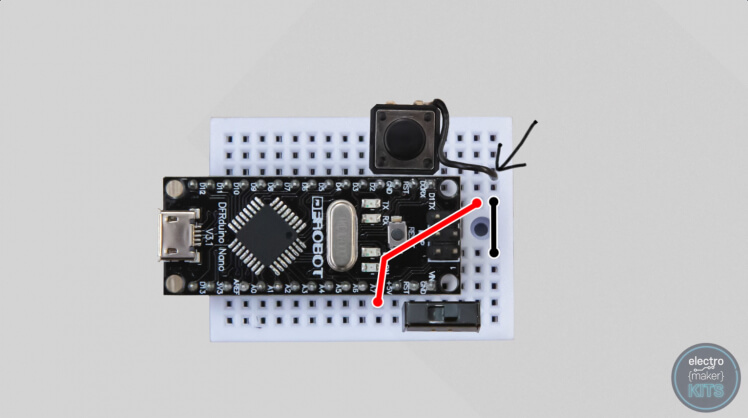
The push-button has its leg adjacent to the cut of leg inserted into the hole closest to the Arduino D2 pin.
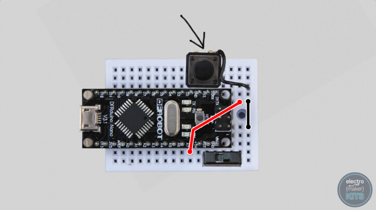
The wire we soldered to it earlier goes into any of the holes in the right-most column.
The positive lead from the battery holder is connected to the centre of the switch using the fourth along, two rows upward.
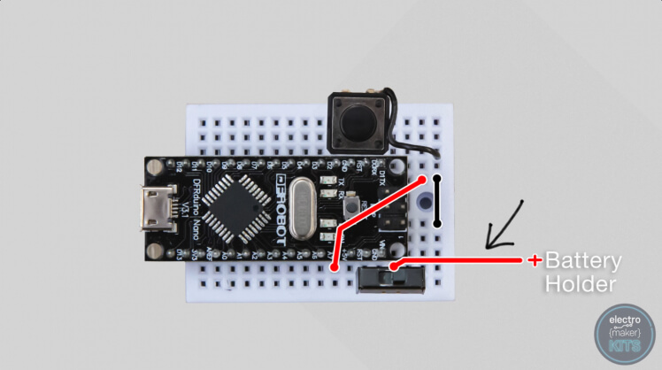
The negative terminal of the battery holder goes to the bottom right corner.

The positive lead from the Neopixels provides power via the seventh hole up, two in from the end.
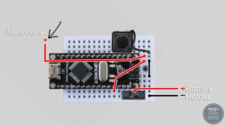
Whilst the grounding is provided through the second hole up from the bottom right corner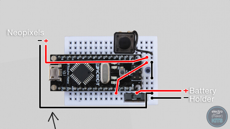
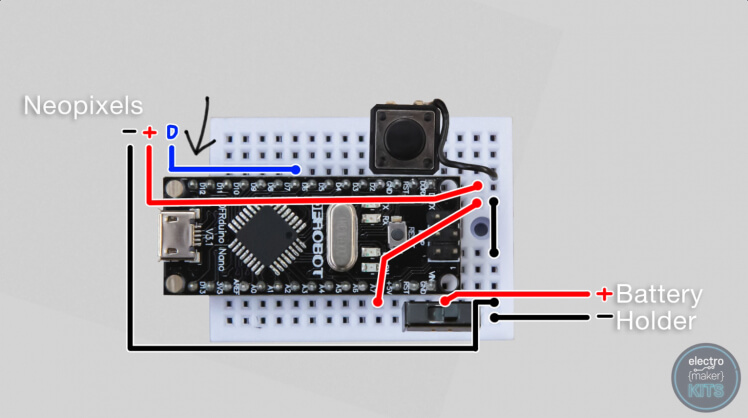
The data comes via pin D6 to the LEDs.
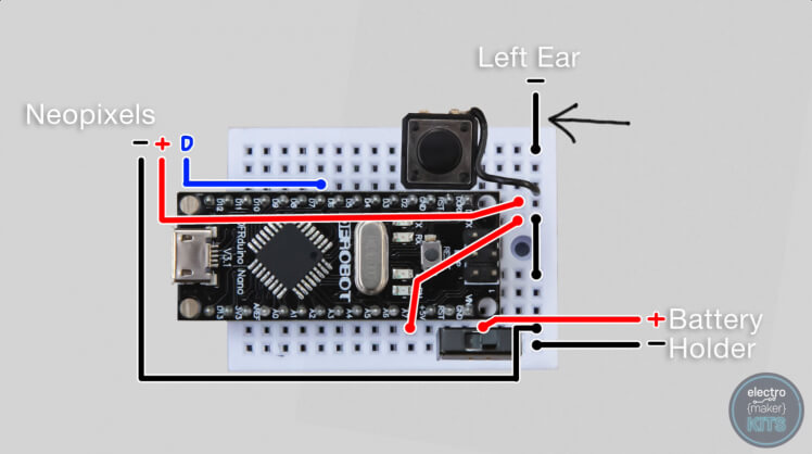
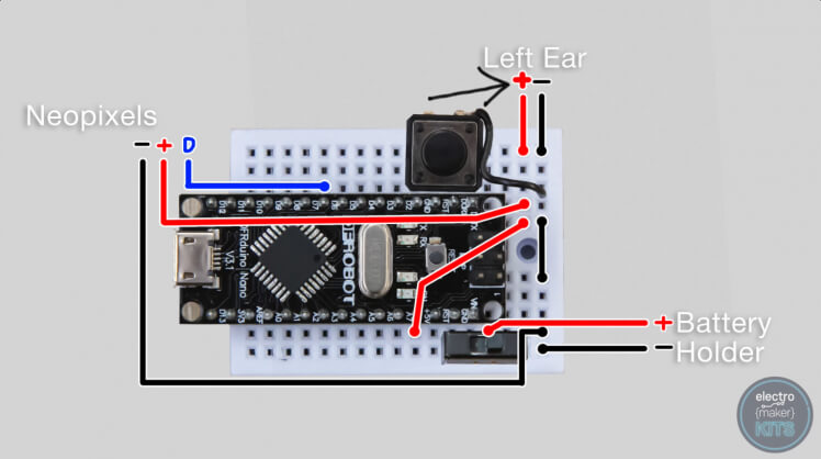
Now moving onto the ears, the negative wire from the left ear goes into the top right hole and the positive wire goes into the hole to its immediate left.
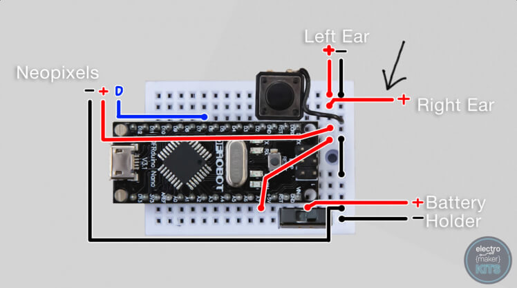
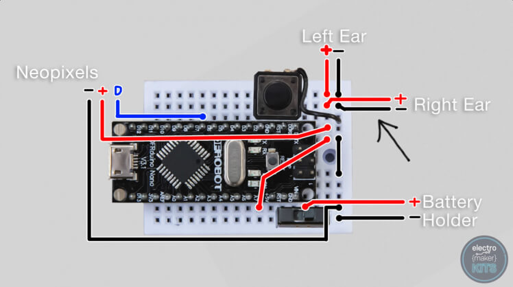
The positive wire for the right ear goes just below the one for the left ear, and its negative wire goes just to the right of this.
Now we have one more additional length of wire to add between the Arduinos ground pin and any available hole on the rightmost column.
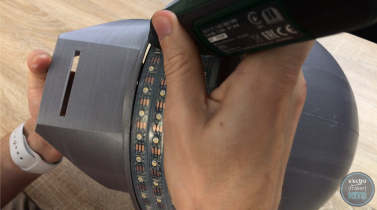
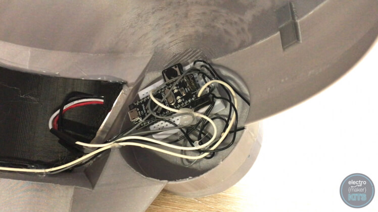
Add four rechargeable AA batteries to your battery holder. You can then check that the wiring is working as intended. If it is we can use some dabs of hotmelt glue to secure everything to the breadboard and then its self-adhesive backing to fix the breadboard to the inside of the right ear.
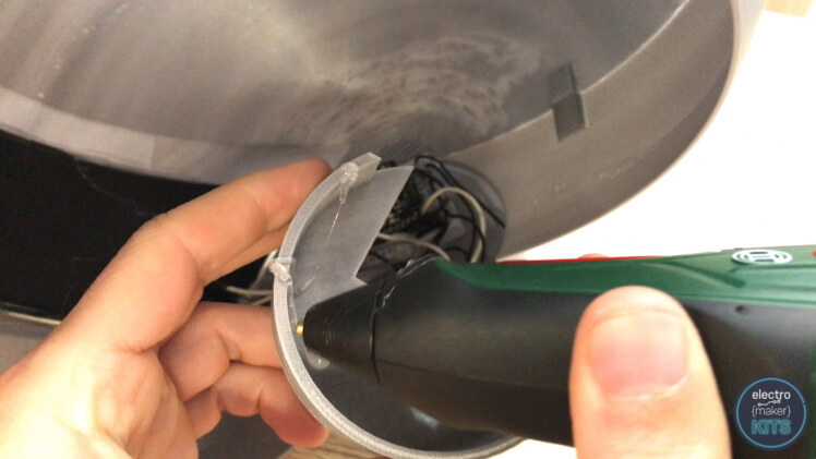
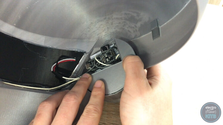
When you fix the breadboard in place use the Arduino cover to help guide its position which should be towards the top and front of the ear. Once you're sure it's in an ideal place you can use some glue to fix the Arduino cover into place ensuring you still have access to the power switch and momentary push button.
Great work, you've finished the project. Now it's time to go show of the fruits of your labour and enjoy your creation.
Where was that 90's retro disco party I heard about this weekend?


Leave your feedback...